


21
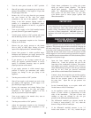
VERTICAL COMBUSTION
AIR INLET
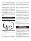
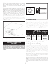
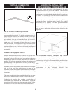
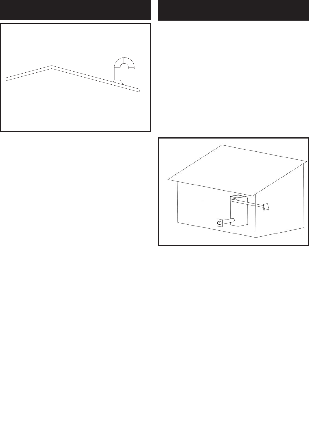
FIG. 30 Air Inlet Cap for Rooftop Termination
The air inlet cap for the vertical roof top air inlet is assembled from
com po nents purchased locally. The air inlet cap consist of two 90°
elbows installed at the point of termination for the air inlet pipe.
The first 90° elbow is in stalled on the rooftop at the highest vertical
point of the air inlet pipe and turned horizontal, the second 90°
elbow is installed on the horizontal outlet of the first elbow and
turned down. A 90° elbow and a 90° street elbow may be used to
make this assembly. If a straight piece of pipe is used be tween the
two elbows, it should not ex ceed 6 inches (150 mm) in length. The
ter mi na tion elbow on the air inlet must be located a minimum of
12 inches (0.30 m) above the roof or above normal levels of snow
accumulation.
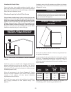
Location of a Rooftop Air Inlet Cap
Incorrect installation and/or location of the air inlet cap can allow
the discharge of flue products to be drawn into the combustion
process on the heater. This can result in incomplete combustion
and potentially hazardous levels of carbon monoxide in the flue
products. This will cause operational problems with the heater and
possible spillage of flue products that can cause personal injury,
death or prop er ty damage.
Installation, location and clearance requirements for the rooftop air
inlet cap in an Intelli-Vent application are the same as the
installation, location and clearance requirements for the rooftop air
inlet cap in the Vertical Direct Vent section of the venting
instructions.
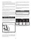
The rooftop combustion air inlet cap and the sidewall flue gas outlet
are located in different pressure zones in an Intelli-Vent system.
Combustion air supplied from outdoors must be free of
contaminants (see Com bus tion and Ventilation Air). To pre vent
recirculation of flue products in to the combustion air inlet, follow
all instructions in this section and re lat ed Direct Vent sections.
In cold climates, the use of type “B” double wall vent pipe or an
insulated single wall pipe is recommended to help prevent moisture
in the cool incoming air from condensing and leaking from the inlet
pipe.
Termination point for the flue products must follow the clearance
requirements in the Horizontal Sidewall Vent
Ter mi na tion section of the Category IV Venting.
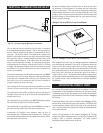
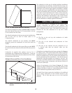
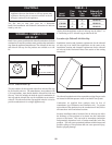
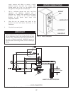
FIG. 31 Horizontal Intelli-Fin Installation with Sidewall
Combustion Air in a Different Pressure Zone
Intelli-Vent systems are installed with a Category IV flue and a
separate combustion air pipe to the outdoors. The Horizontal
Intelli-Vent system terminates the flue at the sidewall and the
combustion air on a sidewall other than the sidewall where the flue
is located. The sidewall flue outlet and sidewall combustion air
intake must terminate in different pressure zones.
Follow all requirements in the General Category IV Venting
sections for proper installation and of venting flue prod ucts
horizontally to the outdoors. All other general installation
requirements must be followed.
The Intelli-Vent System requires the installation of an additional
pipe to supply combustion air from outdoors directly to the
appliance.
HORIZONTAL INTELLI-VENT
WITH SIDEWALL COMBUSTION AIR