


8
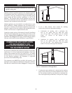
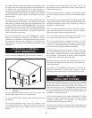
The construction air filter MUST be removed from the
appliance’s air inlet before the appliance is placed in normal
operation. Once the construction air filter is removed, ensure that
either the equipment room is supplied with combustion air from
properly sized combustion and ventilation air openings or a
combustion air duct from a Direct Vent or Intelli-Vent system is
connected to the appliance. The optional Direct Vent and
Intelli-Vent venting sys tems have specific requirements for a
special com bus tion air duct from the outside that is directly
connect ed to the appliance. See the requirements for this
combus tion air duct in the vent ing section for each spe cial ized
vent system.
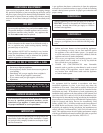
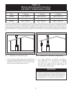
CONSTRUCTION AIR FILTER KITS
TABLE - C
Input Construction
Btu/hr Air Filter Kit
1,500,000
________________________
1,700,000
________________________
2,000,000
KIT4000
________________________
KIT4001
________________________
KIT4002
VENTING
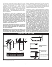
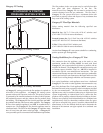
Vent System Options
This appliance has three venting system options. They are: (A)
Category IV Venting system with vertical roof top termination or
sidewall termination of the flue and combustion air supplied from
the mechanical room. (B) Direct Vent with a Category IV flue
and a separate combustion air pipe to the outdoors. The Direct
Vent system ter mi nates both the flue and air inlet in the same
pressure zone. The flue out let and combustion air intake may
ter mi nate on either the sidewall or with a rooftop termination.
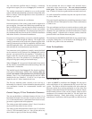
(C) Intelli-Vent with a Category IV flue and a separate
combustion air pipe to the outdoors.The Intelli-Vent system
terminates the flue and the combustion air inlet pipe in different
pressure zones. The Intelli-Vent system may terminate the flue on
the roof top and combustion air intake on the sidewall, the flue
on the sidewall and combustion air from the rooftop or the flue
on the sidewall and combustion air from a different sidewall. All
appliances are shipped from the factory equipped for Category
IV venting. The optional Direct Vent and Intelli-Vent venting
systems will require the installation of specific vent kits and
venting materials. The following is a detailed explanation of the
installation requirements for each venting system, components
used and part numbers of vent kits for each model.
General
Vent installations for connection to gas vents or chimneys must be
in ac cor dance with Part 7, “Venting of Equip ment,” of the latest
edition of the National Fuel Gas Code, ANSI Z223.1, in Canada,
the latest edition of CAN/CGA Stan dard B149 Installation Codes
for Gas Burning Appliances and Equipment or applicable
provisions of the local building codes.
Adequate combustion and ventilation air must be supplied to the
equipment room in accordance with the latest edition of the
National Fuel Gas Code, ANSI Z223.1, in Canada, the latest edition
of CAN/CGA Standard B149 Installation Codes for Gas Burning
Appliances and Equip ment, or applicable provisions of the local
building codes.
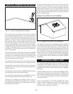
The distance of the vent terminal from adjacent buildings, windows
that open and building openings MUST comply with the latest
edition of the National Fuel Gas Code, ANSI Z223.1, in Canada,
the latest edition of CAN/CGA Standard B149 Installation Code
for Gas Burning Ap pli anc es and Equipment.
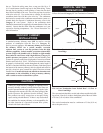
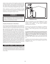
Vent connection is made directly to the flue outlet opening on the
back of the unit. The connection from the ap pli ance vent to the
stack must be made as direct as possible.
IMPORTANT
Examine the venting system at least once a year. Check all
joints and vent pipe connections for tightness. Also, check
for corrosion or deterioration. Immediately correct any prob-
lems observed in the venting system.
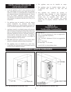
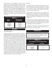
TABLE - D
The Category IV Flue Pipe Sizes
Input Btu/hr Flue Size
1,500,000
________________________
1,700,000
________________________
2,000,000
6"
________________________
7"
_______________________
8"