


34
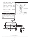
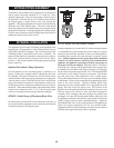
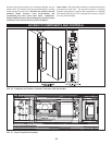
Venting of Gas Valves and Pressure Switches
The diaphragm type gas valve and op tion al gas pressure switches
are pro vid ed with threaded termination points to be vented to the
atmosphere, outside the building. The gas pressure reg u la tion
function is provided by the ratio gas valve which does not require
in stal la tion of a vent line. The di a phragm gas valve and optional
gas pres sure switches are installed in the upper chamber of the
appliance. Threaded vent line connections from components
requiring an external vent line are provided on the component.
These vent line connection points may be accessed by removing
the top jacket panels. Local codes may require the routing of
these bleeds and vents to the atmosphere, outside the building.
Proper routing of vent lines to the atmosphere from the factory
supplied termination points is the re spon si bil i ty of the installing
contractor.
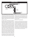
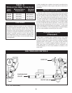
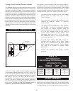
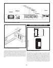
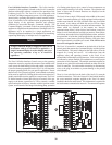
ELECTRICAL CONNECTIONS
ELECTRICAL
JUNCTION BOX
CONTROL
PUMP
FIG. 45 Electric Power Connections - Controls and Pumps
A 120 VAC, 15 Amp, 1 ph, 60 Hz circuit is required for operation
of the integral circulating pump and a 120 VAC, 15 Amp, 1 ph,
60 Hz circuit for the ap pli ance controls are recommended. If a
single electrical service is provided to operate both the controls
and pump, a 120 VAC, 30 Amp, 1 ph, 60 Hz circuit is
recommended. The combustion air blower motor operates on
230 VAC, 3 ph, 60 Hz. This three phase voltage is generated by
the variable frequency drive (VFD) and supplied directly to the
blower motor. NOTE: No 230 VAC electrical service is
required for operation of the combustion air blower.
The appliance, when installed, must be electrically grounded in
accordance with the requirements of the authority having
jurisdiction or in the absence of such requirements, with the latest
edition of the National Electrical Code ANSI/NFPA No. 70. When
the unit is installed in Canada, it must conform to the CAE C22.1,
Canadian Electrical Code, Part 1 and/or local Electrical Codes.
1. All wiring between the appliance and field installed
devices shall be made with type T wire
[63°F (35°C) rise].
2. Line voltage wire exterior to the appliance must be
enclosed in approved conduit or approved
metal clad cable.
3. The pump must run continuously when appliance
is being fired. The Excel 10 temperature controller
will energize the integral circulating pump for
continuous operation when the main power switch
is in the “ON” position and the run stop switch is
in the “RUN” position. If the internal water
temperature drops below 45°F (7.2°C) the pump
will automatically cycle on to help prevent freezing
(see Freeze Protection).
.
4. To avoid serious damage, DO NOT energize the
appliance until the system is full of water. Ensure
that all air is removed from the bypass piping
before beginning initial operation. Se ri ous damage
may result if the ap pli ance is operated without
proper flow.
5. Provide the appliance with proper overload
protection.
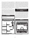
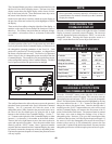
TABLE - R
AMP DRAW DATA
1,000,000 through 2,000,000 Btu/hr Models
APPROXIMATE TOTAL
Blower & Pump Amps
Btu/hr Controls FLA @ 120 AC
1,500,000
__________
1,700,000
__________
2,000,000
15.5
____________
16
____________
16
8.8
__________
8.8
__________
8.8
6.7
____________
7.2
____________
7.2
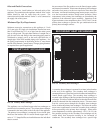
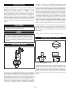
JACKET ASSEMBLY
Inner Jacket - The inner jacket as sem bly is constructed from a
special cor ro sion resistant stainless steel. This includes both the
front primary heat exchanger chamber and the rear sec ond ary heat
exchanger chamber. All screws and fasteners used for assembly of