


30
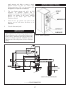
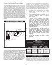
BYPASS PIPING ASSEMBLY
The primary and secondary heat ex chang ers are interconnected
with a bypass and pump mounted in 2 1/2 inch (63.5 mm)
diameter copper pipe. All access to the piping is from the rear of
the appliance. On initial start up, all air must be removed from
the bypass piping to ensure proper water flow through the
appliance. The bypass piping has an air bleed cock located on the
discharge side of the internal pump. This bleed cock should
allow any trapped air in the internal piping to be purged from the
piping before operation. The bypass piping also contains a flow
switch to sense operation of the circulating pump, bulb wells for
tem per a ture sensors and a relief valve(s).
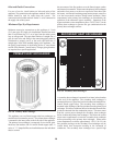
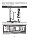
INTEGRAL CIRCULATOR
The appliance has an integral cir cu lat ing pump mounted in the
bypass piping. The pump has a 3/4 H.P. motor wired for 120 volt,
single-phase operation as shipped. The on-off operation of the
circulating pump is controlled by the Excel 10 controller. The
pump will start and run continuously when the power switch is
in the “ON” position and the run/stop switch is in the “RUN”
posi tion. A flow switch installed in the bypass piping assembly
proves water flow.
Optional Intermittent Pump Operation
On-Off operation of the circulating pump is available as an
option. Cycling of the integral pump is controlled by the Excel
10 controller. The pump will start on a call for heat and a flow
switch installed in the bypass piping assembly proves operation.
After the burner cycles off and the call for heat is satisfied, the
pump will continue to operate for a timed period to remove any
residual heat from the combustion cham ber before the pump is
turned off. If the ambient temperature at the tem per a ture sensor
for the Excel 10 drops below 45° F (7.2° C) the circulator pump
will turn on to help prevent freezing of the heat exchanger.
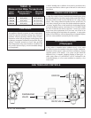
BYPASS - Initial Set-up of Maximum Water Flow
On initial start-up of the Intelli-Fin the maximum water flow to
the two in ter nal heat exchangers must be manually set before the
automatic operation of the bypass begins.
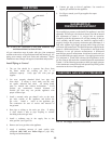
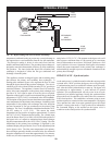
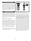
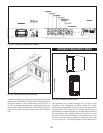
FIG. 41 Bypass Valve and Actuator Assembly
Setting temperature rise on an Intelli-Fin with an automatic bypass
is ac com plished by disconnecting the power leads to the bypass
actuator at the multi-pin connector on the rear of the appliance,
declutching the actuator drive and manually closing the bypass
valve. Manual adjustment of the bypass must not be attempted
if the 24 VAC power leads are connected to the terminals on the
appliance, the ap pli ance is operating or if there is any torque on
the bypass valve by the ac tu a tor. Disconnect the 24 VAC power
leads to the valve actuator. The declutch button on the actuator must
be pushed down and held in the depressed position to disengage
the gear driven motor that operates the valve. The declutch button
must push in easily without forcing its movement. If the button
does not easily move when pushed, the valve is under torque.
Forcing the declutch button in will cause non-warrantable damage
to the actuator. Torque can be removed by disconnecting the power
leads to the valve actuator. With the declutch button fully
depressed, move the ac tu a tor handle till it is perpendicular to the
piping. This fully closes the by pass valve. The position of the
handle is the same as the position of the butterfly in the valve seat.
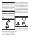
With the bypass fully closed, all inlet water flows through the
secondary heat ex chang er and then through the primary heat
exchanger. No water will flow through the bypass at this time. Turn
the appliance on and allow the burner to come on and fire at full rate
(100% of input as shown on the Command Dis play). Adjust the
field-installed ball valve in the outlet piping from the appliance to
achieve the proper tem per a ture rise for your specific model.
Adjustment to achieve this temperature rise ensures a maximum of
90 GPM to the bypass and pump when in operation.