


23
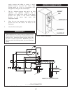
GAS SUPPLY
Verify that the appliance is supplied with the type gas specified on
the rating plate. Consult factory for installations at altitude.
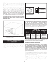
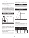
INLET PRESSURE: Measured at the inlet pressure tap on the
appliance gas man i fold. The pressure tap is located upstream
of the redundant gas valve and down stream of the field
installed gas cock.
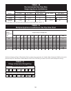
TABLE - K
Inlet Gas Pressure
Natural L. P.
Gas Gas
Max. (Inches-Water Column)
______________________________
Min. (Inches-Water Column)
10.5" w.c.
________
4.0" w.c.
13.0" w.c.
_________
4.0" w.c.
Maximum inlet gas pressure must not exceed the value specified.
Minimum value listed is for the purposes of input adjustment.
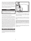
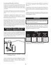
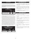
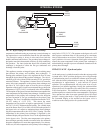
MANIFOLD PRESSURE: Manifold pressure is a differential
pressure measurement made between the high and low pressure
taps at the gas orifice and the pres sure in the transition chamber
where the gas is supplied to the inlet of the combustion air blower.
All manifold gas pressures are noted at full firing rate. The controls
on this appliance may fire the burner from 25% up to 100% of rated
input, based on system demand. Manifold gas pressure will be
reduced as burner input is reduced. All ref er ence gas pressure
measurements must be made at 100% of rated burner input. The
gas manifold pressure is pre-set at the factory by the ratio gas valve.
Ad just ment of manifold pressure is not normally required for
proper operation. The adjustment point on the ratio gas valve is set
at the factory. DO NOT attempt to adjust the settings on the ratio
gas valve. Improper ad just ment of the ratio gas valve may cause
incomplete combustion or non-warrantable burner damage.
TABLE - L
Nominal Manifold Pressure
Settings at Full Fire
Natural L. P.
Input Btu/hr Gas Gas
1,500,000 - 2,000,000
3.5" w.c.
3.5" w.c.
GAS PRESSURE TEST
1. The appliance must be dis con nect ed from the gas
supply piping sys tem during any pressure testing
of that system at a test pressure in excess of 1/2
PSIG (3.5kPa).
2. The appliance must be isolated from the gas supply
piping system by closing a manual shutoff valve
during any pressure testing of the gas supply
piping system at test pressures equal to or less
than 1/2 PSIG (3.5kPa).
3. The appliance and its gas con nec tion must be
leak-tested before placing it in operation.
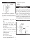
GAS CONNECTION
1. Safe operation of unit requires properly sized gas
supply piping. See gas line sizing data.
2. Gas pipe size may be larger than appliance
connection.
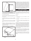
3. Installation of a union at the appliance gas line
connection is re quired for ease of service and
removal of the gas train.
4. Install a manual main gas shutoff valve, outside of
the appliance gas connection and before the gas
valve, when local codes require.
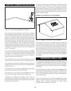
5. A trap (drip leg) MUST be pro vid ed in the inlet of
the gas con nec tion to the appliance.
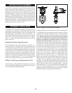
6. The diaphragm gas valve has a bleed port that
requires venting to at mo sphere, outside the
building.
7. Optional gas controls may require routing of bleeds
and vents to the atmosphere, outside the building
when required by local codes.