


32
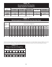
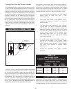
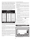
TABLE - Q
Minimum Inlet Water Temperatures
Input Minimum Return Minimum
Btu/hr Temperature Setpoint
1,500,000
___________
1,700,000
___________
2,000,000
105°F (40.6°C)
_______________
90°F (32.2°C)
_______________
70°F (23.9°C)
50°F (10°C)
____________________
50°F (10°C)
____________________
50°F (10°C)
CAUTIONƽ
An appliance allowed to operate at return temperatures
below the specified minimum settings may experience
problems with the operating controls, safety switches,
obstruction of the flue gas passages on the primary heat
exchanger, incomplete combustion and possible flue gas
spillage. Sustained operation at lower than specified
water temperatures may cause hazardous conditions that
may result in personal injury or non-warrantable damage
to the appliance.
A boiler installed above radiation level must be provided with a
low water cutoff device either as part of the unit or at the time of
installation.
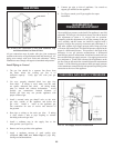
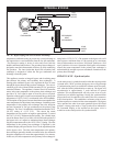
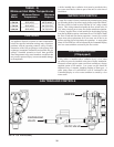
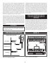
WATER FLOW SWITCH
A water flow switch is factory in stalled in the internal bypass piping
on all heating boilers, hot water sup ply boilers and water heaters.
The flow switch is wired in series with the 24 VAC safety control
circuit. This wiring connection installs the flow switch in the 24
VAC safety circuit to prove water flow before main burner ignition.
A factory supplied flow switch installed in the discharge piping
from the top header requires a minimum flow of 26 GPM to make
the flow switch and start burner operation. A water flow switch
meets most code re quire ments for a low-water cut off device on
boilers requiring forced circulation for operation. A status point
alarm of LowH2OFlow will be indicated in the Command Display
on a low water con di tion as sensed by the flow switch.
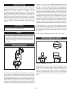
LOW WATER CUTOFF
(If Equipped)
If this boiler is installed above ra di a tion level, a low water
cut-off device must be installed at the time of boiler installation.
Electronic or float type low water cut-offs are avail able as a factory
supplied option on all models. Low water cut-offs should be
inspected every six months, including flushing of float types. A
status point alarm of LowH2OFlow will be indicated in the
Command Display on a low water condition as sensed by a low
water cutoff.
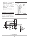
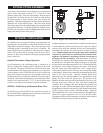
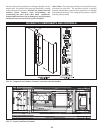
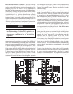
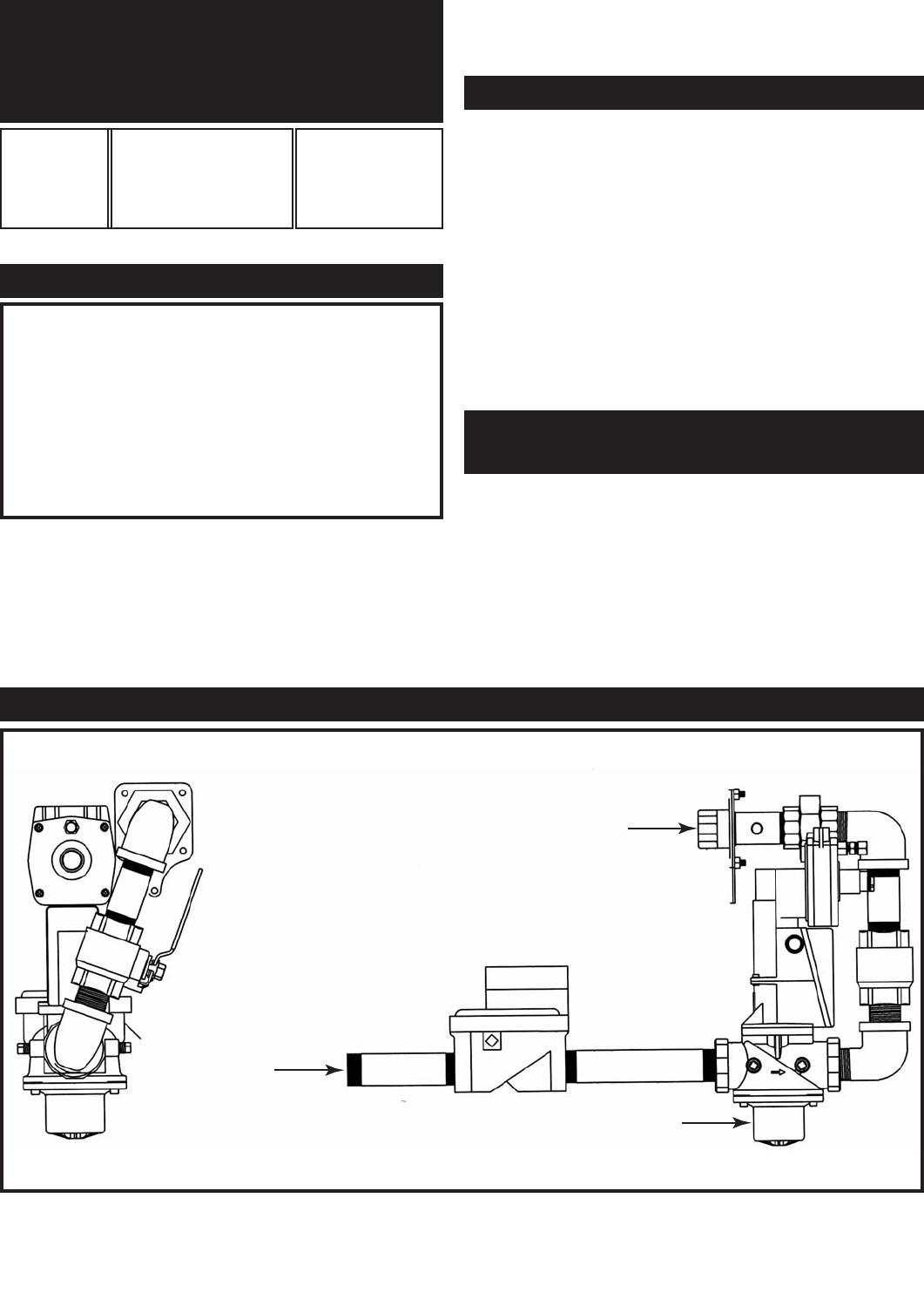
GAS TRAIN AND CONTROLS
DIAPHRAGM
VALVE
ORIFICE
RATIO VALVE
FIG. 42 Gas Train Assembly