


53
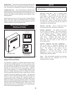
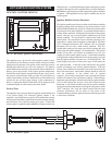
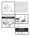
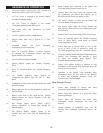
FILTER ACCESS PLATE
FIG. 70 Cleaning the Internal Combustion Air Blower Inlet
Filter
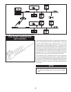
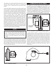
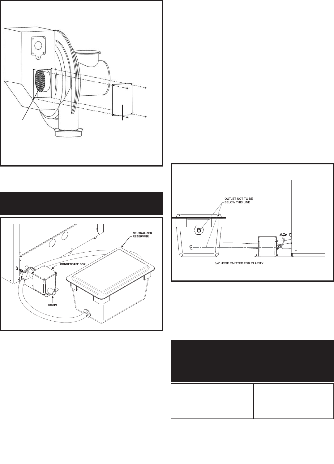
CONDENSATE MANAGEMENT
SYSTEM (Optional)
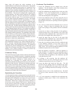
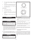
FIG. 71 Location and Connection of Neutralization Reservoir
This high efficiency appliance may operate as a condensing appliance
for extended periods of time based on return water temperatures.
Condensate occurs when the products of combustion are cooled below
their dew point in the heat transfer process. The liquid con den sate
formed from this high efficiency heat transfer pro cess is mildly acidic.
The con den sate will typically have a pH ranging from 4.0 to 5.0 as it
is discharged from the con den sate drain on the rear of the appliance.
The internal jacket area where the condensate is col lect ed (secondary
heat exchanger) is con struct ed from a spe cial corrosion resistant
stainless steel. All ma te ri als external to the appliance in contact with
the con den sate must be corrosion resistant. This is typically
accomplished by gravity requiring a minimum downward slope of
1/4" per foot to ensure proper flow to the condensate management
system and /or a suitable drain. The neutralizer reservoir MUST
always be mount ed on the same lev el or lower than the bottom of the
appliance cabinet. All con den sate pip ing and con nec tions must be
eas i ly ac ces si ble for rou tine main te nance and inspection. Sufficient
lengths of tubing and barbed connectors are supplied in the kit to allow
the neu tral iz er res er voir to be po si tioned to the right, left or rear of the
appliance.
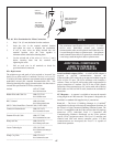
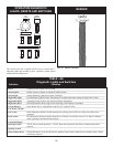
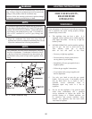
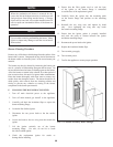
FIG. 72 Condensate Drain Location On Rear of the
Appliance
Operation of the appliance in a full condensing mode for extended
periods of time may produce flue gas condensate in amounts up to
the following volume:
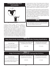
TABLE - BB
Approximate Maximum
Condensate Volumes
Model/Input Btu/hr Gallons Per Hour
1,500,000
_______________________
1,700,000
_______________________
2,000,000
7.3
_______________________
8.3
_______________________
9.7