


22
CAUTIONƽ
Appliances that are shut down or will not operate may
experience freezing due to convective airflow in the air
inlet pipe connected to the appliance.
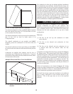
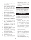
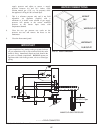
The flue and air inlet duct sizes for a Horizontal
Intelli-Vent Installation with Sidewall Combustion Air Inlet are
listed by unit size.
SIDEWALL COMBUSTION
AIR INLET
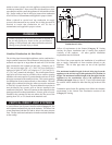
Intelli-Vent systems installed with sidewall terminations for both
com bus tion air and flue products must pur chase the termination
caps from the appliance manufacturer. The sidewall air inlet cap
and sidewall vent cap for flue products are available as a vent
kit.
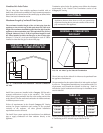
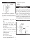
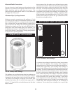
FIG. 32 Sidewall Vent Cap
The part numbers for the required sidewall air inlet and flue cap
kit are listed by unit size. The manufacturer, in accordance with
CSA re quire ments, must furnish both the sidewall air inlet and
flue cap. Each kit includes the both the special com bus tion air
inlet cap and the sidewall flue cap for installation on an ex te ri or
sidewall. The sidewall air inlet cap supplied in the kit is sized to
provide combustion air for a single appliance only.
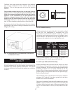
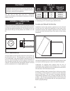
TABLE - J
Flue Air Inlet Sidewall Air
Input Cap Cap Inlet & Flue
Btu/hr Size Size Cap Kit
1,500,000
___________
1,700,000
___________
2,000,000
6"
_______
7"
_______
8"
6"
_______
8"*
_______
8"
HDK3018
________________
HDK3019
________________
HDK3020
*Piping from the appliance to the air inlet cap may be either 7" or
8" connecting to an 8" sidewall cap provided in the kit.
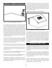
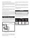
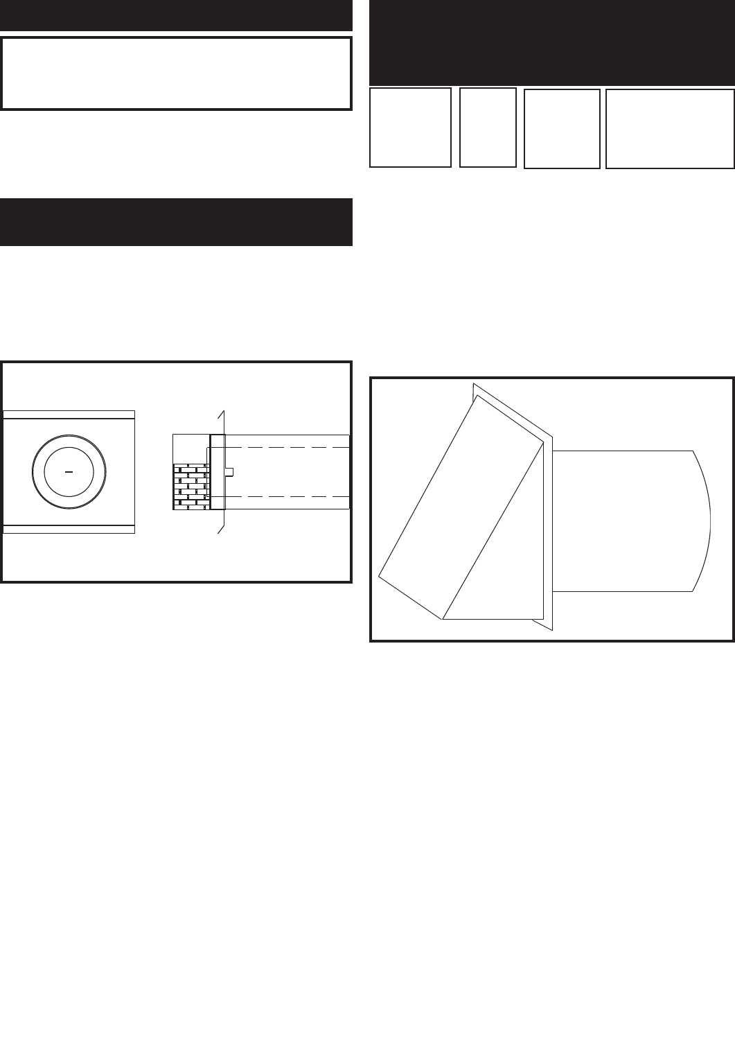
Location of a Sidewall Air Inlet Cap
Installation, location and clearance requirements for the sidewall
air inlet cap in an Intelli-Vent application are the same as the
installation, location and clearance requirements for the sidewall
air inlet cap in the Hor i zon tal Direct Vent section of the venting
instructions.
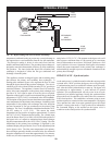
FIG. 33 Air Inlet Cap for Sidewall Termination
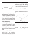
The sidewall combustion air inlet cap and the rooftop flue gas outlet
are located in different pressure zones in an Intelli-Vent system.
Combustion air supplied from outdoors must be free of
contaminants (see Com bus tion and Ventilation Air). To pre vent
recirculation of flue products in to the combustion air inlet, follow
all instructions in this and related sec tions.
Incorrect installation and/or location of the air inlet cap can allow
the discharge of flue products to be drawn into the combustion
process on the heater. This can result in incomplete combustion
and potentially hazardous levels of carbon monoxide in the flue
products. This will cause operational problems with the heater and
possible spillage of flue products that can cause personal injury,
death or prop er ty damage.