


57
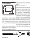
SEQUENCE OF OPERATION
1. The power switch is placed in the “ON” position and
the run/stop switch is in the “RUN” position.
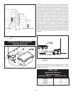
2. 120 VAC Power is supplied to the con trol junction
box and to the integral pump.
3. 120 VAC Power is supplied to the con trol
Transformer, Ignition Module and Excel 10.
4. The bypass valve will synchronize on initial
startup only.
5. 24 VAC is supplied to all low volt age controls.
6. Integral pump starts and is proven by a Flow
Switch.
7. Command Display Set Point (Operating
Temperature) is set to call for heat.
8. Excel 10 Controller initiates a start-up sequence
by checking the Tem per a ture Sensors and input
signals from the safety controls.
9. Excel 10 enables the Ignition Mod ule.
10. Ignition Module enables the Vari able Frequency
Drive.
11. Excel 10 Controller drives the Variable Frequency
Drive.
12. The Variable Frequency Drive sup plies the
Combustion Air Blower with 230 VAC 3 phase
power.
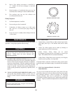
13. Combustion Air Blower starts op er a tion and drives to 100%
speed for prepurge.
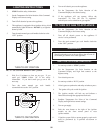
14. Blower makes the low air switch contacts to enable the
Ignition Module.
15. Blower cycles down to 50% speed and the Ignition
Module initiates the heat-up sequence of the Hot
Surface Igniter.
16. Hot Surface Igniter proves 1800°F (982°C)
Ignition Temperature by current draw through the
Ignition Module.
17. The Ignition Module supplies voltage to the
Variable Ratio Gas Valve and the Redundant Gas
Valve.
18. Relay contacts prove operation of the Igniter, Gas
Valves and Safety Switches to the Excel 10.
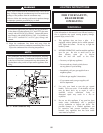
19. Variable Ratio Gas Valve senses the pressure from
the Combustion Air Blower and supplies gas to
the orifice and into the Blower inlet to pre-mix.
20. The Gas/Air mixture is forced into the Burner and
out of the Burner Ports under pressure.
21. Hot Surface Igniter lights the Gas/Air mixture and
then serves as a flame sensor to prove Main Burner Flame
by rectification.
22. Burner is now in a soft start fir ing at 50% of rated input.
23. Excel 10 Controller signals the Variable Frequency
Drive to adjust blower speed based on desired
water temperature Set Point.
24. Burner input rate is variable down to 25% of rate
or up to 100% of rate as required to satisfy the
Set Point pro grammed into the Command Display.
25. Excel 10 Controller senses Inlet Water Temperature to the
Primary Heat Exchanger and provides a signal
to adjust the floating point Bypass Valve
(based on return/inlet control choice).
26. Bypass Valve adjusts position to maintain an inlet
temperature to the Primary Heat Exchanger above the
dew point of flue products.
27. Operation of the Bypass Valve main tains water
temperatures above the dew point of flue products
to ensure that condensate formation occurs only
in the Secondary Heat Exchanger.
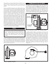
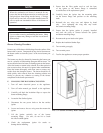
Heat Transfer Process
28. Burner Input continues to increase until water
temperature reaches the Set Point temperature.
29. Burner Input may stabilize at a fixed rate where
demand equals input.
30. Burner Input will decrease rate when water
temperature exceeds tem per a ture Set Point and
demand.
31. Heated products of combustion pass over the
Primary Heat Exchanger trans fer ring heat to the
water.