


68
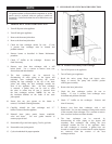
TEMPERATURE/PRESSURE GAUGE
This boiler is equipped with a dial type temperature/pressure
gauge. This gauge is factory installed in the out let side of the
boiler bypass piping. The gauge has one scale to read system
pressure and a separate scale to read water temperature in °F. The
tem per a ture/pressure gauge is provided to meet code
requirements. Water temperatures can be more accurately
monitored from the data provided in the Command Display.
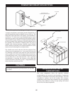
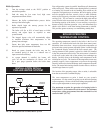
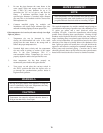
TYPICAL HEATING BOILER
INSTALLATIONS
General Plumbing Rules
1. Check all local codes.
2. For serviceability of boiler, always install unions.
3. Always pipe pressure relief valve to an open drain.
4. Locate system air vents at high est point of system.
5. Expansion tank must be installed near the boiler
and on the suction side of the system pump.
6. Support all water piping.
PLACING THE BOILER
IN OPERATION
Pre-Start Check List
1. Review the location of the boiler, clearances from
combustible surfaces and available service
clearances.
2. Review the installed Vent System. Ensure that all
vent components are Category IV material with
adequate clearance from combustibles.
3. Ensure that the boiler condensate drain and all vent
system condensate drains are properly routed to
an ac cept able floor drain or neutralization system.
4. Ensure that an optional condensate neutralization
system is properly in stalled if required by codes.
5. Review the vent termination point for proper
location and clearances.
6. Ensure that proper volumes of com bus tion and
ventilation air are pro vided to the mechanical room.
If a separate combustion air pipe is used, ensure
that it is properly sized, sealed and terminated.
7. Review the water piping from the boiler to the
system. The boiler must be installed in a primary/
secondary piping system. Review the diameter and
equivalent length of the installed piping to and
from the boiler to ensure proper flow.
8. Ensure that a properly sized primary system pump
is installed with an expansion tank.
9. Check system pressure. Ensure a minimum of 12
PSI and not more than the rated pressure of the
relief valve.
10. Review the installed gas piping from the meter to
the boiler. Ensure that the gas pipe, meter and any
regulators are adequately sized.
11. Review the field wiring and elec tri cal service for
both the boiler controls and pump. Ensure that the
electrical service(s) is adequately sized.
12. Review wiring to an energy man age ment system
and wiring to any remote temperature sensors.
Boiler Set-Up
13. Ensure that the boiler and piping system are full of
water. Bleed all air from the secondary loop and
bypass piping on the boiler.
14. Check system for any water leaks.
15. Check system for installation of glycol or water
treatment.
16. Turn on power to the primary system pump and
the integral boiler secondary pump and verify
operation.
Boiler Operational Checks
17. Turn the boiler main power switch to the “ON”
position and the run/stop switch to the “STOP”
position.
18. Verify operation of the Excel 10 and Command
Display.
19. Program the adjustable points from the Command
Display.
20. Turn the run/stop switch to the “RUN” position to
start boiler operation. Note: The bypass must go
through the synchronization process before
start-up begins.
21. Push the resets for low water lev el, high water
temperature and flame failure.
22. Carefully follow the bypass ad just ment procedure
to set maximum flow to the boiler at 90 GPM. Verify
by check ing temperature rise while burner is firing at
100% of rated input.
23. Install a manometer on the gas supply to the boiler
and verify minimum gas supply pressure as the
burner fires at 100% of rated input.
24. Verify operation of safeties as necessary (low water
cut-off, high limit, gas pressure, etc.).
25. Turn the run/stop switch to the “STOP” position.
26. Verify that all adjustable points in the Command
Display are set as required.
27. Reconnect any wiring disconnected during the
boiler set-up.