


29
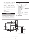
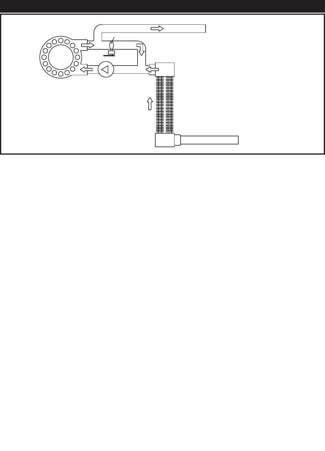
INTEGRAL BYPASS
HOT
WATER
OUTLET
SECONDARY
HEAT
EXCHANGER
COLD
WATER
INLET
PRIMARY
HEAT
EXCHANGER
PUMP
BYPASS VALVE
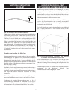
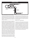
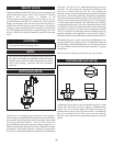
FIG. 40 Bypass Piping with Valve Actuator and Pump
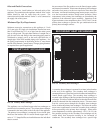
temperature conformal coating to prevent any corrosive damage to
the copper tubes or cast iron head ers from the low pH condensate.
The protective coating is brown in color and covers both the
headers and finned tube surfaces. The secondary heat exchanger is
designed to maximize heat transfer efficiency by fully condensing
flue products. The inner jacket that houses the secondary heat
exchanger is designed to collect the flue gas con den sate and
discharge it from the jacket.
This appliance contains an integral bypass and circulating pump
that con nects the primary and secondary heat exchangers. A
floating-point automatic bypass valve regulates the flow of water
through the bypass between the two heat exchangers. The valve is
a butterfly type valve with an EPDM seat and a 24 VAC gear driven
motorized actuator. The appliance’s internal Excel-10 con trol ler
senses inlet water temperature to the primary heat exchanger and
pro vides a 24 VAC signal to open or close the valve as required.
Operation of the bypass is based on an assumed flue gas dewpoint
temperature of 130°F (54.4°C) as referenced in the ANSI standards.
The dewpoint of flue gasses becomes the minimum acceptable inlet
water temperature for the primary heat exchanger. Sustaining water
tem per a tures in the primary heat exchanger above the dewpoint
prevents formation of flue gas condensate on the primary heat
exchanger. The Excel 10 es tab lish es a dead band around the 130°F
(54.4°C) setting of +1.8°F (2°C). This means the actual
temperature can vary positive or negative approximately 2° around
the 130°F (54.4°C) minimum desired setting. The variable input
rate of the burner from 25% to 100% will also affect the po si tion of
the bypass valve as it adjusts to maintain primary heat exchanger
(Bypass) temperatures above the 130°F (54.4°C) setting. The inlet
temperature to the primary heat exchanger is displayed by the
command display and provides the Excel 10 the adjustment point
for the bypass valve. The inlet water tem per a ture to the primary
heat exchanger generally should not remain below the minimum
dewpoint temperature for more than approximately five minutes.
In this case, the inlet temperature to the primary heat exchanger is
rarely below 125°F (51.7°C). The actuator on the bypass valve will
take between a minimum time of 180 seconds up to a maximum
time of 300 seconds to move from a “full closed” position to a “full
open” position or vice versa. Operation of the bypass valve actuator
assures that water temperature in the primary heat exchanger is
maintained high enough to prevent condensate formation on the
primary heat exchanger.
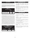
BYPASS VALVE - Synchronization
As the main power is switched on and/or when the run/stop switch
is placed in the “RUN” position, the bypass valve will go through
a synchronization process to establish a reference point for op er a -
tion. After the initial synchronization on start-up, the bypass will
resynchronize in approximately 2 week intervals of normal
operation. This resynchronization will only occur in an off cycle
operation of an installed appliance. During the synchronization
process the Excel 10 controller will overdrive the valve actuator to
a full closed position. This establishes a reference point to assure
quicker re sponse to variation in inlet water temperature. The bypass
valve op er ates best when it can start operation from a full closed
position. A status point mode of Byp Synch will be in di cat ed in
the Command Display as the actuator on the bypass valve is
overdriven to the closed position for synchronization.