


74
TABLE - GG
Common Water Manifold Size
For Multiple Water Heater
Hot Water Supply Boiler Installations
Btu/hr Input Temperature Rise
Pipe sizing chart provides minimum pipe size for
common manifold piping to ensure adequate flow.
Common Manifold
Number of Units Size (Min)
1
_______________________
2
_______________________
3
_______________________
4
_______________________
5
_______________________
6
3"
_______________________
4"
_______________________
4"
_______________________
5"
_______________________
6"
_______________________
6"
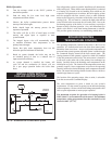
PUMP OPERATION
1. The water heater or hot water supply boiler has a
properly sized integral circulating pump. This
pump is sized to circulate water between the heater
and storage tank only.
2. The internal pump is sized to the heater input and
water chemistry spec i fi ca tions noted in “Water
Chemistry.”
3. The diameter and length of the piping installed
between the storage tank(s) and water heater must be
properly sized based on the equivalent length
specifications.
4. The pump must run continuously when the water
heater or hot water supply boiler is firing. This is the
stan dard operating system for a water heat er or hot
water supply boiler.
An intermittent pump control function with an all bronze pump
is installed as standard equipment on all water heater systems.
The pump will operate only while there is a “Call for Heat” and
for a timed period after the water temperature set point is satisfied
to remove any residual heat from the com bus tion chamber.
5. Lubricate pump to manufacturers recommendations.
Pump damage due to inadequate lubrication is
non-warrantable.
This is a highly sophisticated heat exchanger system, designed to
carry water in such a way that it generates a scouring action which
keeps all interior sur fac es free from build-up of impurities. The
straight-line, four pass design of the tubes sends water into the
headers at a properly rated velocity. The configuration of the
headers, in turn, creates a high degree of turbulence which is
sufficient to keep all con tam i nants in suspension. This “scour ing
action” provides greater cost sav ings for owners. Tubes are always
able to transfer heat at peak efficiency. Every surface within this
water con tain ing section is of a non-ferrous material, providing
clear, clean, rust-free hot water. Straight copper tubes finned on
the outside for maximum heat transfer and glass lined, cast iron,
one piece, cored headers make up an entirely rust-proof unit. On
all mod els, header inspection plugs in the primary heat exchanger
can be removed for field inspection and clean ing of copper tubes.
Each of the heat exchangers may be removed from the unit.
HEAT EXCHANGER
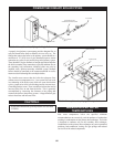
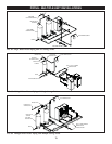
6. The operating temperature sensor for a water
heater or hot water supply boiler is installed in
inlet piping to the water heater or hot water supply
boiler.
The operating sensor must be installed in the tapping provided in
the lower 25% of the stor age tank to achieve proper operation. As
shipped from the factory, the op er at ing sensor is installed in a bulb
well mounted in the inlet piping to the water heater. When the
pump cycles off in normal operation, this sensor location may not
adequately sense a quick drop in tem per a ture from a draw of hot
water from the storage tank. Placing the sensor in the tapping
provided on the storage tank will improve temperature response
and prevent short cycles of operation when a water heater is
equipped with the optional intermittent pump feature.
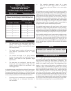
The standard integral pump on this water heater is sized based on
in stal la tion of a single storage tank and heater in close proximity.
If the number of fittings and straight pipe exceeds the specified
maximum equiv a lent number of straight feet for a specified diameter
of pipe, non-war rant ableoperational problems may be experienced.
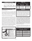
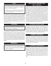
When installing multiple water heaters and/or multiple storage
tanks, the diameter of the inner connecting pipe and all fittings must
be increased. An increase in pipe diameter will decrease head loss
in the system piping and ensure proper flow. Proper pipe size
between the heater and storage tank MUST be maintained to ensure
that the standard pump supplied on the water heater will maintain
desired flow.
NOTE:
Minimum pipe diameters and maximum length
specifications must be per the requirements in this section.