


15
sealant to ensure a proper seal at the appliance con nec tion and the
air inlet cap connection. Dryer vent or flex duct should use a screw
type clamp to seal the vent to the appliance air inlet and the air inlet
cap. Proper sealing of the air inlet pipe ensures that combustion
air will be free of contaminants and sup plied in proper volume.
When a sidewall or vertical roof top combustion air supply
system is dis con nect ed for any reason, the air inlet pipe must be
resealed to ensure that combustion air will be free of
con tam i nants and supplied in proper volume.
DANGER ƽ
Failure to properly seal all joints and seams as required in
the air inlet piping may result in flue gas recirculation,
spillage of flue prod ucts and carbon monoxide emissions
causing severe personal injury or death.
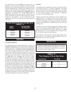
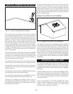
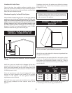
Combined Combustion Air Inlet Points
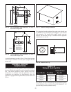
The air inlet pipes from multiple ap pli anc es can be combined to a
single common connection if the common air inlet pipe has a cross
sectional area equal to or larger than the total area of all air inlet
pipes connected to the common air inlet pipe. {Example: two 8"
(20.3 cm) air inlet pipes [50.3 in
2
(324.5 cm
2
) area each] have a
total area of 100.6 in
2
(645.2 cm
2
) requires a 12" (30.5 cm) [113.1
in
2
(729.7 cm
2
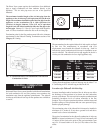
] common air inlet pipe.} The air inlet point for mul -
ti ple boiler air inlets must be pro vid ed with an exterior opening
which has a free area equal to or greater than the total area of all air
inlet pipes connected to the common air in let. This exterior opening
for com bus tion air must connect directly to the outdoors. The total
length of the combined air inlet pipe must not exceed a maximum
of 100 (30.5 m) equivalent feet. You must deduct the restriction in
area provided by any screens, grills or louvers installed in the
common air inlet point. These are common on the sidewall air inlet
openings and some rooftop terminations. Screens, grills or louvers
installed in the common air inlet can reduce the free area of the
opening from 25% to 75% based on the materials used.
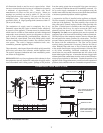
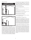
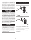
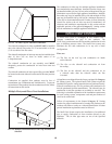
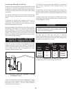
VERTICAL DIRECT VENT SYSTEMS
A Vertical Direct Vent System is in stalled with a Category IV flue
and a separate combustion air pipe to the outdoors. The Direct Vent
system ter mi nates both the flue and air inlet in the same pressure
zone. The flue out let and combustion air intake must both terminate
on the rooftop.
Follow all requirements in the General Category IV Venting
sections for proper installation and of venting flue prod ucts
vertically to the outdoors. All other general installation
requirements must be followed.
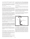
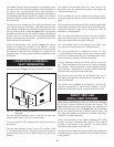
The Direct Vent system requires the installation of an additional
pipe to supply combustion air from outdoors directly to the
appliance. The air inlet pipe must use one of the spec i fied
materials.
The maximum installed length of the air inlet pipe from the
appliance to the air inlet cap is 100 equivalent feet (30.48 m) in
length. The maximum in stalled length of the flue pipe from the
appliance to the termination cap is 100 equivalent feet
(30.48 m) in length. Subtract 5 feet (1.52 m) of equivalent length
for each 90° elbow installed in either the flue pipe or the air inlet
pipe.
Termination point for the flue products must follow the clearance
requirements in the Vertical Vent Termination sections of the
Category IV Venting.
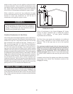
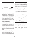
FIG. 20 Vertical Direct Vent Installation with Rooftop
Combustion Air Inlet
3'
12"