


69
Boiler Operation
28. Turn the run/stop switch to the “RUN” position to
start boiler operation.
29. Push the resets for low water lev el, high water
temperature and flame failure.
30. Observe the boiler synchronization process before
start-up of the boiler begins.
31. Boiler should begin the start-up process for the
sequence of operation.
32. The boiler will fire at 50% of rated input on initial
start-up and adjust input as required to meet
system demand.
33. The integral bypass valve will automatically adjust
to maintain min i mum inlet temperatures to the
primary heat exchanger.
34. Ensure that inlet water temperature does not fall
below the specified min i mum for the boiler.
35. Based on system demand, the boiler may run for
an extended period of time at a reduced rate of
input to maximize efficiency.
36. As system demand is satisfied, the burner will
cycle off and the com bus tion air blower will run
for a post purge operation before the boiler shuts
down.
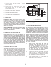
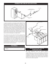
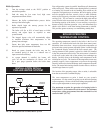
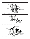
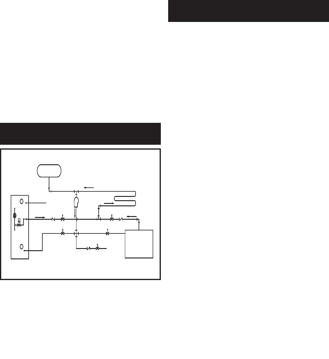
INSTALLATION WITH A
CHILLED WATER SYSTEM
EXPANSION
TANK
HEATING AND
COOLING COIL
GAS SUPPLY
PUMP
WATER
SUPPLY
CHILLER
FIG. 82 Installation with a Chilled Water System
Pipe refrigeration systems in parallel. Install duct coil downstream
at the cooling coil. Where the hot water heating boiler is connected
to a heating coil located in the air handling units which may be
exposed to refrigeration air circulation, the boiler piping system
must be equipped with flow control valves or other automatic
means to prevent gravity circulation of the boiler water during the
cooling cycle. The coil must be vented at the high point and hot
water from the boiler must enter the coil at this point. Due to the
fast heating capacity of the boiler, it is not necessary to provide a
ductstat to delay circulator op er a tion. Also, omit thermostat flow
checks as the boiler is cold when heat ing thermostat is satisfied.
This provides greater economy over main tain ing standby heat.
BOILER OPERATING
TEMPERATURE CONTROL
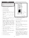
The operating temperature control for the boiler is the Excel 10
controller. It is located on the back side of the front control panel,
behind the front access door. Access to adjust the temperature set
point and other owner/operator adjustable points is made through
the Command Display located on the front control panel. The
sensing element for the operator is placed in a bulb well installed
in the inlet connection to the boiler. The outlet sensor is located in
a bulb well on the outlet side of the primary heat exchanger top
header. Carefully observe the discharge water temperature on the
initial boiler on cycles. The location of the tem per a ture sensor may
generally require a lower temperature set point on the operating
control to achieve the de sired discharge water temperature from the
boiler. The return/inlet sensing element lo ca tion allows a boiler to
sustain longer burner on cycles.
The location of the operating sensor, inlet or outlet, is selectable
from the screen on the Command Display.
The exact temperature set point is based on your system’s
requirements. Set the control set point(s) to the desired operating
water temperature. Observe the boiler discharge tem per a ture after
each set point adjustment to ensure proper operation.
The maximum set point for operation of a heating boiler is
220°F (104.4°C) on a standard Excel 10 control. The minimum
tem per a ture setting programmed into this stan dard Excel 10
control is 100°F (37.7°C).