


54
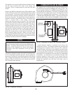
Many codes will require the acidic condensate to be
neu tral ized before it can be placed in a drain system. The optional
condensate management system consists of a neutralizer kit to
control the pH of the liquid discharged to a drain system. The
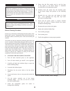
neutralizer in the condensate man age ment system con sists of an
industrial grade, non-corrosive plastic reservoir for collection of
the condensate. The reservoir is charged with a reagent grade
calcium carbonate. The initial calcium carbonate fill is shipped
installed in the reservoir. The top to the reservoir is sealed and
held in place with two straps. It is not necessary to open the
reservoir before placing the neu tral iz er in service. The reagent
grade calcium carbonate should fill approximately 3/4 of the
reservoir in an even layer over the bottom. The condensate outlet
from the appliance must be piped to the reservoir inlet. A barbed
fitting is provided for connection to the appliance condensate drain
hose (lower hose). The drain from the condensate drain tee in the
vent ing system may also be routed to the reservoir inlet for disposal
of any condensate formed in the flue. This would be accomplished
by adding a field installed tee to the hose assem bly. Ensure that a
trap is provided in the drain line from the flue to prevent flue gases
from escaping with the con den sate. The condensate collects in the
reservoir where it is in direct contact with the calcium carbonate.
As the reservoir fills, it provides an extended residence time to
neutralize the condensate. The neutralized condensate exits from
the reservoir outlet to the condensate trap.
When the condensate level in the reservoir raises to the drain, the
pH is controlled to a range of 6.5 to 7 before exiting the system. (A
pH of 7 is neutral. As the pH number increases in numerical value,
the relative acidity of the discharge decreases.) The neutralized
condensate may then be discharged into a suitable drain system
without fear of damage to the drain system. Ensure that the top
remains on the reservoir keeping it sealed to prevent any
contamination to the treatment process.
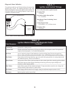
Condensate Testing
The initial fill of reagent grade calcium carbonate should sus tain
neutralization for 3 months of operation. An appliance operating
at higher temperatures will produce condensate at lower levels
allowing the calcium carbonate to remain ef fec tive as a
neutralizer for a maximum of 6 months. The pH of the
neutralized condensate discharged from the reservoir should be
checked at 30 day intervals. A pH meter or indicating test strips
may be used to monitor the relative acidity of the con den sate.
When the pH of the condensate discharged from the reservoir
can not be maintained above a pH of 6.0, the calcium carbonate
must be recharged. Recharge packages of reagent grade calcium
carbonate are available from your distributor.
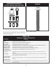
Replenishing the Neutralizer
All of the depleted calcium carbonate must be removed from the
reservoir and properly disposed of. Rinse and clean the reservoir
thoroughly before adding the new charge to the system. Ensure
that the piping to and from the reservoir is clear with no
obstructions. Add the new reagent grade calcium carbonate in
an even layer over the bottom of the reservoir. Replace the top
on the reservoir, replace the two straps to secure the top and
return the appliance to service. Check the related piping for leaks
on the initial firing after the system is recharged.
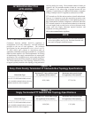
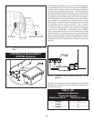
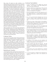
Condensate Trap Installation
1. Locate the condensate trap kit shipped loose with the
appliance. The kit includes a sheet metal mounting base,
two (2) nuts and the condensate trap.
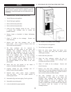
2. Install the condensate trap mounting base on the rear of the
appliance in the lower left-hand corner as depicted in
Figure 73. Use the pre-drilled holes on the appliance to
secure the mounting base to the appliance.
3. Secure the condensate trap to the base using the two (2)
nuts supplied with the kit. The trap should be oriented so
that the barb connections are pointing toward the appliance
(Figure 73).
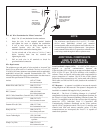
4. Use a level to ensure that the condensate trap is level on
its base. Failure to keep the condensate trap level can
result in the spillage of flue products from the condensate
trap.
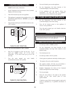
5. Locate the two hoses exiting the back of the appliance.
Attach the larger hose on the appliance to the lower barb
connection on the condensate trap. Secure the hose to the
barb with a field supplied hose clamp (Figure 73).
6. Attach the upper hose on the unit to the upper barb
connection on the condensate trap. Secure the hose to the
barb with a field supplied hose clamp (Figure 73).
7. Route the wire connector harness from the condensate trap
to the matching connector on the lower back of the
appliance as shown in Figure 73. This is the blocked drain
safety switch. This switch will shut the appliance off if the
condensate trap becomes too full of liquid.
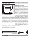
8. Place the appliance in operation. While the appliance is
firing, check the 1/2" connection on the condensate trap for
flue gas spillage. If spillage is detected, check the routing
of the hoses from the appliance to the condensate trap and
verify that the trap is level.
9. If spillage is still occurring, shut the appliance off.
Remove the four (4) screws securing the top cover to the
condensate trap and remove the cover (Figure 73).
10. Locate the plastic ball inside the float tube. The ball
prevents flue gas spillage from the condensate trap when
there is not enough liquid in the trap to raise it and drain.
Verify there is nothing under the ball causing it to not seat
properly.
11. Replace the top cover on the condensate trap. Re-install
the four (4) screws removed in Step 9 to secure the top
cover.
12. A 1/2" pipe connection is supplied on the condensate trap.
Connect a suitable pipe or tube to this connection (see
Figure 73).