


58
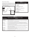
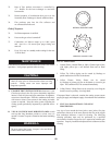
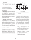
32. Rate of flue product movement is controlled by
“V” Baffles on the heat exchanger to maximize
heat transfer.
33. Heated products of combustion then pass over the
Secondary Heat Exchanger to absorb additional heat.
34. Flue products pass into the flue collector and
are exhausted from the unit.
End of Sequence
35. Set Point temperature is satisfied.
36. Power to the gas valves is turned off.
37. Combustion Air Blower ramps up to 100% speed
and runs for a 30 second post purge timing and
turns off.
38. Excel 10 is now in a standby mode waiting for the next
“Call for Heat”.
MAINTENANCE
Listed below are items that must be checked to ensure safe reliable
oper a tions. Verify proper operation after servicing.
CAUTIONƽ
Label all wires prior to disconnection when servicing
controls. Wiring errors can cause improper and
dangerous operation.
A. EXAMINE THE VENTING SYSTEM at least once a year.
Check more often in the first year to determine inspection
interval. Check all joints and pipe connections for tightness,
corrosion or deterioration. Flush the condensate drain hose
with water to clean. Clean screens in the venting air intake
system as re quired. Have the entire system, in clud ing the
venting system, pe ri od i cal ly inspected by a qualified service
agency.
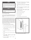
B. VISUALLY CHECK MAIN BURNER FLAMES at each
start up after long shutdown pe ri ods or at least every six
months. A burner viewport is located on the burn er mounting
flange.
WARNINGƽ
The area around the burner viewport is hot and direct
contact could result in burns.
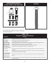
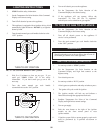
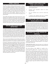
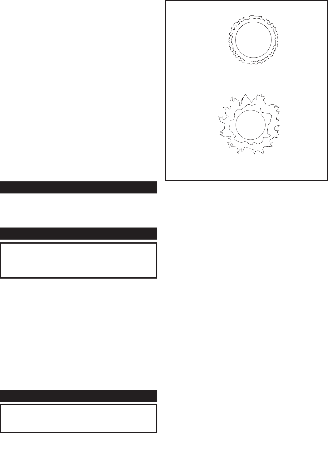
ABNORMAL BURNER FLAME
NORMAL BURNER FLAME
FIG. 76 Flame Pattern
1. Normal Flame: A normal flame at 100% of burner input is blue,
with slight yellow tips a well defined flame and no flame
lifting.
2. Yellow Tip: Yellow tipping can be caused by blockage or
partial obstruction of air flow to the burner.
3. Yellow Flames: Yellow flames can be caused
by blockage of primary air flow to the burner or excessive gas
input. This condition MUST be corrected immediately.
4. Lifting Flames: Lifting flames can be caused by over firing the
burner, excessive primary air or high draft.
If improper flame is observed, examine the venting system, ensure
proper gas supply and adequate supply of combustion and ventilation
air.
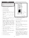
C. FLUE GAS PASSAGEWAYS CLEANING
PROCEDURES:
Any sign of soot around the inner jacket, outer jacket, flue pipe
connections, burner or in the areas between the fins on the copper
heat exchanger indicates a need for clean ing. The following
cleaning procedure must only be performed by a qualified
serviceman or installer. Proper ser vice is required to maintain safe
operation. Properly installed and ad just ed units seldom need flue
cleaning.