


62
9. Carefully reinstall the heat ex chang er if removed
from the appliance.
10. Reinstall inner rear jacket panels, bypass piping
and condensate hoses. Use new gasket material
to ensure a proper air seal.
11. Reassemble all water piping. Test for leaks.
12. Reassemble rear outer jacket pan els.
13. Cycle unit and check for proper operation.
H. LUBRICATION
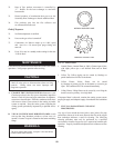
Combustion Air Blower: Each combustion air blower should
be checked every 6 months. Clean internal filter to blower as
required when installed in a dust or dirt contaminated location.
See Combustion Air Blower in the com po nent section for
cleaning procedure. The motor and bearings on the com bus tion
air blower are sealed and per ma nent ly lubricated requiring no
addition of oil or lubricants.
Water Circulating Pump: Inspect pump every 6 months and oil
as necessary. Use SAE 30 non-detergent oil or lu bri cant
specified by pump manufacturer.
I. COMBUSTION AND VENTILATION AIR
Check frequently to be sure the flow of combustion and
ventilation air to the boiler is not obstructed. Combustion and
ventilation air must be provided to the mechanical room with
openings sized per the requirements of the National Fuel Gas
Code when the appliance is installed with a standard Category
IV vent system. The optional Direct-Vent and Intelli-Vent
systems use a separate combustion air pipe to bring in
combustion air from the outdoors directly to the appliance.
Ensure that the construction air filter is NOT used for continuous
service after the con struc tion phase.
J. CONTROL CIRCUIT VOLTAGE
This appliance uses a transformer to supply a low voltage control
circuit. The voltage on the secondary side should be 24 to
28 VAC when measured with a voltmeter. A secondary voltage
of 18 VAC or less supplied to 24 VAC components may cause
operational prob lems. A 5 AMP circuit breaker is provided on
the secondary side of the trans form er. The circuit breaker is
located on the left front control panel. A tripped circuit breaker
indicates a short in the 24 VAC controls that must be corrected.
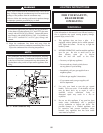
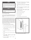
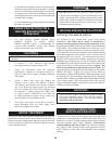
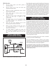
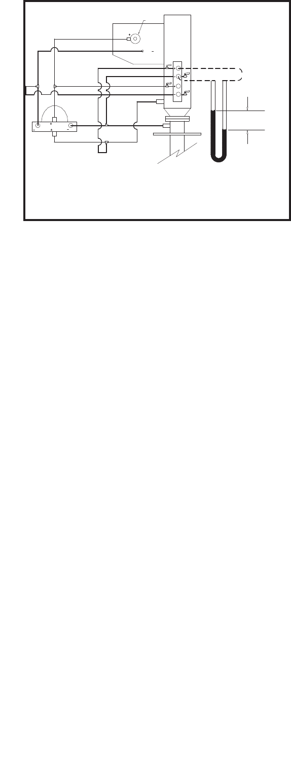
MANIFOLD AIR PRESSURE
– – – – = FIELD CONNECTED
3.5" W.C. = ai
r
P
GAS VALVE
(TOP VIEW)
BURNER
AIR
GAS
GAS
AIR BOX
(FRONT VIEW)
GAS
BLOWER
ORIFICE
AIR
GAS
AIR
GAS
FIG. 79 Measuring Combustion Air Pressure Differential to
Ratio Gas Valve
K. COMBUSTION AIR MEASUREMENT
This appliance uses a variable speed combustion air blower to
operate the combustion process and venting system. A single
combustion air blower is used to supply combustion air to the
burner. The discharge air from the blower is factory pre-set and is
not field ad just able. The blower and transition are mounted on the
top of the burner. The blower is enclosed inside of the top chamber.
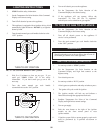
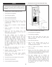
There is a pressure test tree located in the top chamber of the
appliance. This pressure test point tree can be accessed by swinging
out the front control panel. The pressure test tree is mounted on
the front edge of the combustion air blower. It consists of an angle
support and four labeled test cocks. There is one cock for + air and
one for - air, one cock for + gas and one for - gas. Differential air
pres sure measurement at the combustion air blower will utilize both
the + air and - air test points.
1. Open the front control panel and swing the
controls out. Locate the pressure test tree on the
front edge of the combustion air blower. The +
and - air pressure terminals will be used to check
differential air pressure from the blower discharge to
the burner inlet. Each air pressure connection
point will have a small manual cock to attach a hose.
2. Connect a hose from the + air and the - air to each
of the two sides of a manometer. This will allow
the two pressure points to be measured at the same
time. Open the two air pressure test point cocks.
3. Set the Command Display to a set point which will
fire the burner at 100% of rated input.