


59
NOTE:
All gaskets/sealant on disassembled components or jacket
panels must be replaced with new gaskets/sealant on
reassembly. Gasket and sealant kits are available from your
distributor.
CAUTIONƽ
When a Category IV vent system is disconnected for any
reason, the flue must be reassembled and resealed according
to the vent manufacturer’s instructions.
D. BURNER MAINTENANCE
The burner should be removed for in spec tion and cleaning on an
annual basis. An appliance installed in a dust or dirt contaminated
atmosphere will require inspection and cleaning on a more frequent
schedule. An appliance installed in a contaminated environment may
require cleaning of the burner on a 3 to 6 month schedule or more
often, based on severity of the con tam i na tion. The fan assisted
combustion process may force airborne dust and dirt contaminants,
contained in the combustion air, into the burner. With sustained
operation, non-combustible contaminants may reduce burner port
area, reduce burner input or cause non-warrantable damage to the
burner.
Use extreme care when operating an appliance for temporary heat
during new construction. Airborne contaminants such as dust, dirt,
concrete dust or dry wall dust can be drawn into the burner with the
combustion air and block the burner port area. An external
combustion air filter is provided with the appliance. The combustion
air filter is for Temporary Use Only and MUST be removed when
the appliance is placed in normal service. An additional filter is
located inside the transition chamber, at the inlet to the combustion air
blower, to also prevent particulate matter and small foreign objects
from entering the blower and burner. This internal filter should be
checked and cleaned on a six month interval or more often in a
contaminated environment. See the Combustion Air Blower section of
this manual for cleaning instructions. The burner of an appliance used
for temporary heat with out a combustion air filter in stalled will
probably require a thor ough cleaning before the unit is placed into
normal service.
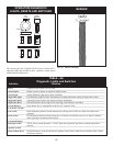
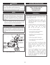
BURNER REMOVAL AND CLEANING
Access to the burner will require the following steps:
a. Turn off main electrical power to the appliance.
b. Turn off main manual gas shutoff to the appliance.
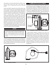
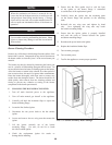
c. Remove the outer control panel cover. Open the
control panel and remove the screws from the
lower front edge of the radiused front outer jacket
panel. Lift the edge of the radiused panel and
locate the internal screws attaching the back edge
of the radiused panel. Reach through the control
panel opening with a 5/16” nut driver and loosen
the 2 internal screws holding the rear edge of the
radiused panel. Pull the panel slightly forward and
remove it. Remove the screws along the front and
rear edge of the top outer jacket panel to remove
the jacket top. This allows access to the
components in the top of the appliance.
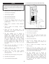
d. Disconnect the gas supply connection to the internal
gas train at the field installed union.
e. Remove the air inlet pipe con nec tion to the
boiler/water heater.
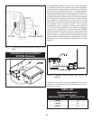
f. Remove the insulation blanket* on top of the heat
exchanger. Note: Take care not to tear insulation
blanket on removal.
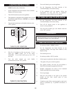
g. Disconnect the blower motor power wires at the
connection to the VFD.
h. Disconnect the power wires to the gas valves, flow
switch and pressure switches (if equipped).
Multiple pin connectors are used at all of these
components for ease of service.
i. Remove the sensing tubes from the air ratio gas
valve to the combustion air blower.
j. Remove the 6 nuts holding the blower assembly
to the blower and remove the blower assembly.
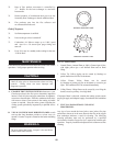
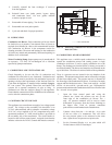
k. Disconnect the power wire to the hot surface igniter.
l. Remove the hot surface igniter. The hot surface
igniter is fragile. Use care to prevent impact
damage to the silicon carbide igniter surface when
removing the igniter.
m. Remove the 8 nuts holding the burn er to the heat
exchanger.
n. The burner can now be lifted ver ti cal ly out of the
heat exchanger cavity.
o. Use care to prevent damage to the woven burner
port surface on removal.
* Insulation jacket is tucked under the control panel assembly and
cannot be “removed” without removing the control panel.