


33
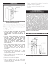
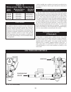
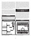
RELIEF VALVE
This unit is supplied with a relief valve(s) sized in accordance with
ASME Boiler and Pressure Vessel Code, Sec tion IV (“Heating
Boilers”). The re lief valve(s) is installed in the
ver ti cal position and mounted in the hot water outlet. No valve is
to be placed between the relief valve, and the unit. To prevent water
damage, the discharge from the relief valve shall be piped to a
suitable floor drain for disposal when relief occurs. No reducing
cou plings or other restrictions shall be installed in the discharge
line. The discharge line shall allow complete drainage of the valve
and line. Relief valves should be manually operated at least once
a year.
CAUTIONƽ
Avoid contact with hot discharge water.
NOTE:
The gas train and controls assembly provided on this unit
have been tested under the applicable American National
Standard to meet minimum safety and performance criteria
such as safe lighting, combustion and safety shutdown
operation.
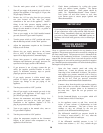
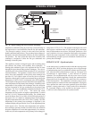
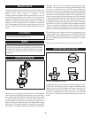
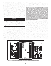
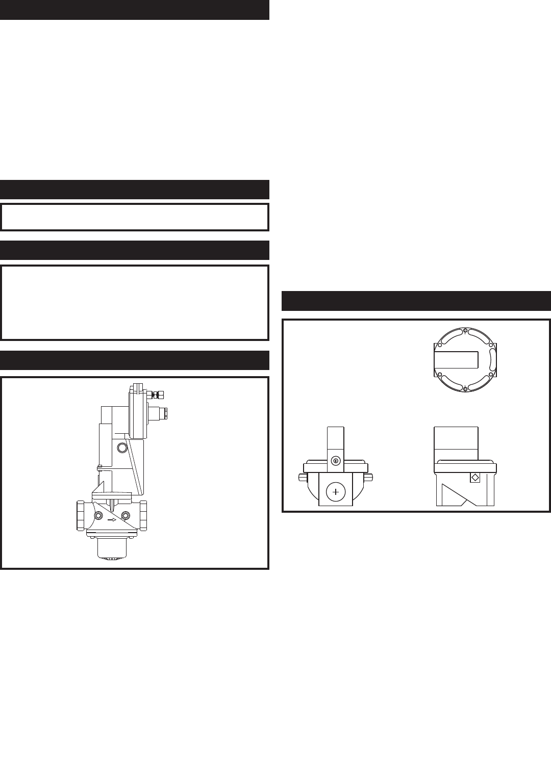
RATIO GAS VALVE
FIG. 43 Ratio Gas Valve
The main gas valve supplying gas to the burner on this appliance
utilizes a pressure regulating electro hydraulic actuator providing a
slow opening, fast closing safety shut off and air/gas ratio control
for the gas combustion process. This gas valve controls the
pressure difference across the re stric tion in the gas supply line as a
func tion of the pressure difference across the combustion air supply
to the burn er. The actuator maintains a con stant air to gas ratio as
the volume of air changes based on the operation of the combustion
air blower. The valve is a 1:1 differential pressure air/gas ratio
controller. The valve adjusts the same pressure difference on the
gas side as it senses on the air side. The valve performs the
functions of safety shutoff, constant pressure regulation and air/gas
ratio control. Slow open ing and safety shutoff is accomplished by
operation of an electro hydraulic cylinder. Full closing of the valve
seat occurs in less than 0.8 seconds when the valve is de-energized.
A visual stroke position indicator is provided on the valve assembly
to in di cate the position of the valve seat. Operation of the gas valve
in com bi na tion with the combustion air blower allows the burner
input rate to vary from 25% to 100% based on temperature demand.
There is no need for an ad di tion al upstream constant gas pressure
regulator internally to the appliance as long as the gas supply is
maintained within the specified minimum and max i mum pressures.
The manifold pressure is preset at the factory and adjustment is not
usually required if gas supply pressure is maintained within the
specified range. If the manifold pressure is to be mea sured, follow
the “Gas Manifold Pres sure Measurement Procedure” for proper
measurement.
There are no serviceable parts on the ratio gas valve actuator.
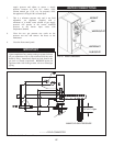
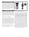
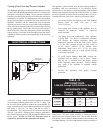
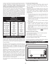
DIAPHRAGM GAS VALVE
FIG. 44 Diaphragm Gas Valve
A diaphragm type gas valve is also provided in the gas train. As the
second valve seat in the gas train, it supplies a redundant safety
shutoff valve seat in the gas supply to the burner to ensure safe
operation in the remote event of a gas valve failure. The diaphragm
gas valve is energized with 24 VAC power at the same time the
ratio gas valve is powered in the op er a tion al sequence to ignite the
burn er.