


26
1. Turn the main power switch to “OFF” position.
2. Shut off gas supply at the manual gas cock in the as
piping to the ap pli ance. If fuel supply is LP gas, shut
off gas supply at the tank.
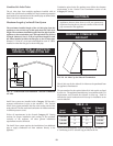
3. Remove the 1/8" hex plug from the gas pressure
test port located on the inlet gas supply
connection at the rear of the appliance. Install a
fitting in the inlet pressure tapping suitable to
connect to a manometer or magnahelic gauge.
Range of scale should be 14 inch w.c. or greater to
check inlet pressure.
4. Turn on gas supply at the field installed manual
gas cock, turn on LP gas at tank if required.
5. Turn the power switch to “ON” po si tion and ensure
that the Run/Stop switch is in the “Run” position.
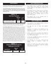
6. Adjust the temperature setpoint on the Command
Display to call for heat.
7. Observe the gas supply pressure as the burner
fires at 100% of rated in put. Percent of burner
input will be displayed on the Command Display.
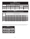
8. Ensure inlet pressure is within specified range.
Minimum and Maximum gas supply pressures are
specified in Gas Supply section of this manual.
9. If gas pressure is out of range, contact the gas
utility, gas supplier, qualified installer or service
agency to determine necessary steps to provide
proper gas pressure to the control.
10. If gas supply pressure is within normal range,
proceed to remove gas manometer and replace
pressure tap fittings in the gas piping to the
appliance.
11. Turn the power switch to “OFF” po si tion.
12. Shut off gas supply at the manual gas cock in the
gas piping to the ap pli ance. If fuel supply is LP
gas, shut off gas supply at the tank.
13. Remove the manometer and related fittings from
gas pressure test port at the inlet gas supply
connection to the appliance. Replace 1/8" hex
plug in gas pressure test port and tighten.
14. Turn on gas supply at the manual valve, turn on
LP gas at tank if required.
15. Turn the power switch to “ON” position.
16. Adjust the temperature setpoint on the Command
Display to the desired water temperature so the
appliance will call for heat.
17. Check burner performance by cycling the system
while you observe burner response. The burner
should ignite promptly. Flame pattern should be
stable, see “Maintenance-Normal Flame Pattern.”
Turn system off and allow burner to cool, then
cycle burner again to ensure proper ignition and
flame characteristics.
IMPORTANT
Upon completion of any testing on the gas system, leak test
all gas connections with a soap solution while the main
burner is firing. Immediately repair any leak found in the
gas train or related components. DO NOT operate an
appliance with a leak in the gas train, valves or related gas
piping.
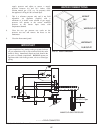
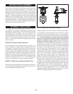
CHECKING MANIFOLD
GAS PRESSURE
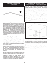
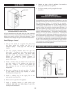
There is a pressure test tree located in the top chamber of the
appliance. This pressure test point can be ac cess ed by swinging out
the front control panel. The pressure test tree is mounted on the
front edge of the com bus tion air blower. It consists of an angle
support and four test cocks. There is one cock for positive air and
one for negative air, one cock for positive gas and one for negative
gas. Manifold pressure measurement will utilize both the positive
and negative test points for gas.
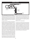
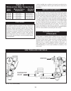
1. Open the front controls panel and swing the
controls out. Locate the pressure test tree on the
front edge of the combustion air blower. The positive
and negative gas pressure terminals will be used to
check differential gas pressure from the gas manifold
and the air box. Each gas pressure connection
point will have a small manual cock to attach a hose.
2. Connect a hose from the positive gas and the negative
gas to each of the two sides of a manometer. This will
allow the two pressure points to be measured at
the same time. Open the two gas pressure test
point cocks.
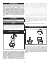
3. Set the Command Display to a set point which will
fire the burner at 100% of rated input.
4. As the appliance comes on and fires, record the
inches of water column of displacement on both
sides of the manometer. The sum of these two
readings as they are effected by the two gas
pressures is the differential man i fold pressure.
5. The differential manifold gas pres sure should be
3.5 inches of water column (+ 0.1" w.c.) when the
burner is firing at 100% of rated input.
6. If the differential manifold pres sure is not 3.5
inches water column (+ 0.1" w.c.), recheck the gas