


96
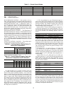
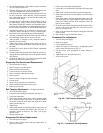
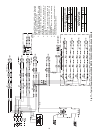
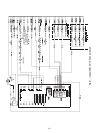
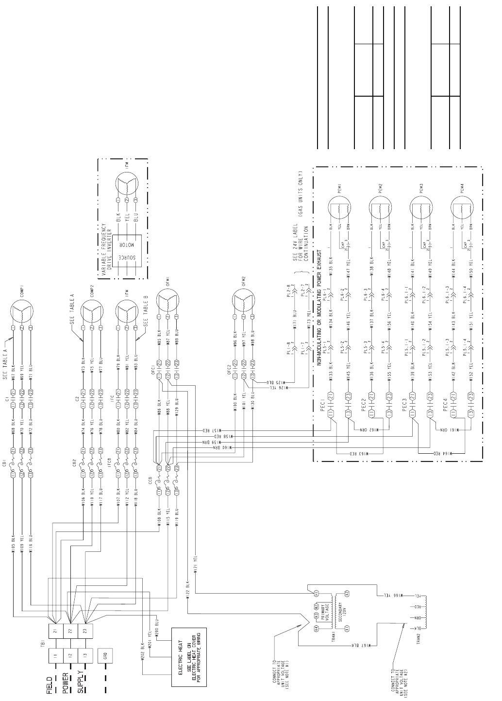
Fig. 77 — Typical Power Schematic 48EJ,EK,EW,EY024-034; 208/230-3-60 and 460-3-60
NOTES:
1. Connect TRAN1 to H4 for 460 v units. Connect to
H3 for 230 v. If 208/230 v units are run with a
208-v power supply, connect to H2.
2. Connect TRAN2 to black lead for 460 v units.
Connect to orange lead for 230 v units. If 208/230
v units are run with a 208-v power supply, con-
nect to red lead.
3. Circuit breaker must trip amps are equal to or
less than 156% FLA for CB1 and CB2. All others
are 140%.
4. If any of the original wire furnished must be
replaced, it must be replaced with Type 90 C wire
or its equivalent.
5. Compressors and/or fan motors are thermally
protected.
6. Three phase motors are protected against pri-
mary single phasing conditions.
TABLE 1A
The following compressors have two
parallel wires run from TB1 to the
compressors.
Compressor
Model
Voltage
Wire
Quantity
06D-537 208/230-3-60 2
TABLE 2B
The following fan motors have two
parallel wires run from
TB1 to the fan motors.
Indoor
Motor
Voltage
Wire
Quantity
20 HP 208/230-3-60 2