


30
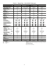
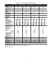
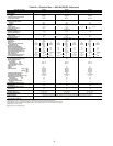
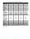
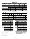
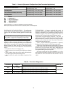
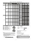
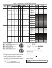
Table 5 — Controls Options and Configurations (Non-Thermostat Applications)
LEGEND
*With DIP Switch No. 5 configured to OPEN (Occupied Heat Enabled).
NOTE: Space temperature sensor and remote start/stop switch are field-supplied.
STAGED GAS UNIT APPLICATIONS — The rooftop units
may be ordered with an optional factory-installed staged gas
control system that monitors heating operation of the rooftop
unit.
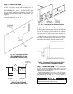
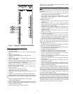
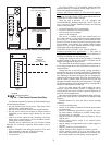
Install Supply-Air Thermistors (Staged Gas Units Only)
—
Supply-air thermistors are a field-installed factory-provided
component. Three supply-air thermistors are shipped with
staged gas units and are inside the heating section. Thermistor
wires must be connected to SGC (staged gas controller) in the
heating section. See Table 6 and Fig 24. The supply-air ther-
mistors should be located in the supply duct with the following
criteria:
• downstream of the heat exchanger cells
• equally spaced as far as possible from the heat exchanger
cells
• a duct location where none of the supply air thermistors
are within sight of the heat exchanger cells
• a duct location with good mixed supply air portion of the
unit.
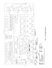
THERMISTORS — All units are equipped with a supply air
thermistor (SAT) located in the supply fan discharge and an
outdoor air thermistor (OAT) located in the outdoor air hood.
Variable air volume (VAV) units are supplied with a return air
thermistor (RAT) located on the return air damper support.
CONSTANT VOLUME APPLICATIONS — The units, as
shipped, are operable as stand-alone units, using either a stan-
dard (mechanical or electronic) 2-stage heat, 2-stage cool ther-
mostat, or with an electronic room sensor and a timeclock to
establish unit start and stop times.
With a standard thermostat (programmable is optional),
heating and cooling operation is set by space temperature.
With a space sensor and timeclock, the machine will operate
at default values unless they are changed using appropriate in-
put devices. The space sensor senses space temperature and
may be equipped with a timed override feature, which allows
unit operation during unoccupied periods.
The space sensors may be used in multiples of 4 or 9 to
achieve space temperature averaging. The use of a space sensor
also allows the unit to be turned on and off from a remote
signal.
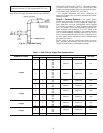
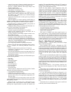
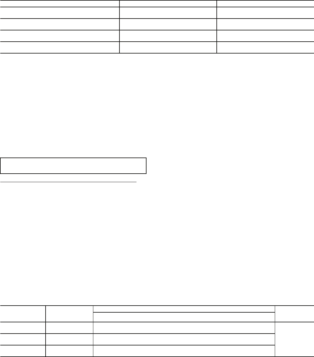
Table 6 — Thermistor Designations
UNIT CONFIGURATION DEFAULT COOLING DEFAULT HEATING
CV or VAV Unit with SPT Sensor
Unoccupied Cooling — 90 F (32 C) (SPT)
Occupied Cooling — NA
Unoccupied Heating — 55 F (13 C) (SPT)
Occupied Heating — NA
CV Unit with SPT Sensor and Remote
Start/Stop Switch
Unoccupied Cooling — 90 F (32 C) (SPT)
Occupied Cooling — 78 F (26 C) (SPT)
Unoccupied Heating — 55 F (13 C) (SPT)
Occupied Heating — 68 F (20 C) (SPT)
VAV Unit Remote Start/Stop Switch Only
Unoccupied Cooling — 90 F (32 C)(SPT)
Occupied Cooling — 55 F (13 C) SPT)
Unoccupied Heating — 55 F (13 C) (RAT)
Occupied Heating — 68 F (20 C) (RAT)*
VAV Unit with SPT Sensor and Remote
Start/Stop Switch
Unoccupied Cooling — 90 F (32 C) (SPT)
Occupied Cooling — 55 F (13 C) (SAT)
Unoccupied Heating — 55 F (13C) (SPT)
Occupied Heating — 68 F (20 C) (RAT)*
CV — Constant Volume
NA — Not Available
RAT — Return-Air Temperature
SAT — Supply-Air Temperature
SPT Space Temperature
VAV — Variable Air Volume
IMPORTANT: An accessory field-supplied Navigator dis-
play module is required for all staged gas control units.
THERMISTOR
PIN
CONNECTION
POINT
FUNCTION AND LOCATION
PART NO.
Thermistors
SAT 1 J8 – 1,2 (SGC)
Supply Air Thermistor (SAT) — Inserted into supply section
underneath the gas heat section (factory-provided, field-installed)
HH79NZ016SAT 2 J8 – 3,4 (SGC)
Supply Air Thermistor (SAT) — Inserted into supply section
underneath the gas heat section (factory-provided, field-installed)
SAT 3 J8 – 5,6 (SGC)
Supply Air Thermistor (SAT) — Inserted into supply section
underneath the gas heat section (factory-provided, field-installed)