


45
Thermostat Wiring (CV Only)
— Install a Carrier-approved
accessory thermostat assembly (per current price pages)
according to the installation instructions included with the ac-
cessory or these instructions. Locate the thermostat on a solid
interior wall in the conditioned space to sense the average
temperature.
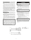
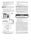
Route the thermostat cable or equivalent single leads of
colored wire from the subbase terminals to the low-voltage
connection as shown on unit label wiring diagram and in
Fig. 32.
NOTE: For wire runs up to 50 ft, use no. 18 AWG (American
Wire Gage) insulated wire (35 C minimum). For 50 to 75 ft,
use no. 16 AWG insulated wire (35 C minimum). For over
75 ft, use no. 14 AWG insulated wire (35 C minimum). All
wire larger than no. 18 AWG cannot be directly connected at
the thermostat and will require a junction box and splice at the
thermostat.
Set heat anticipators to 0.1 for all voltages. Settings may be
changed slightly to provide a greater degree of comfort for a
particular installation.
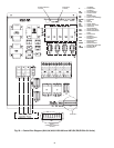
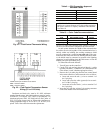
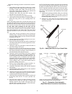
Sensor Wiring (CV or VAV)
— The temperature sensor is
wired into the unit control board. See Fig. 33.
The unit is controlled with a T-55 or T-56 (CV only) zone
sensor. Terminal TH (T-56) or T1 (T-55) on the sensor is con-
nected to T1 of the base control board. Terminal COM (T-56)
or T2 (T-55) on the sensor is connected to T2 on the base con-
trol board. If a T-56 set point override sensor is used, the over-
ride connection SW on the sensor is connected to T3 on the
base control board.
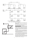
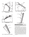
If more than sensor is being used and averaged, sensors
must be wired in multiples of 4 or 9. See Fig. 34.
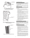
Heat Interlock Relay
— VAV units require a field-supplied
heat interlock relay (HIR) to drive the air terminal wide open
when in heat mode. Heat Interlock relay part number is
HN61KK040. See Fig. 35 for HIR wiring.
Remote Field Control
— A switch closure across terminals R
and W1 on TB-3 will initiate the Occupied mode. This can be
done manually as well as through a field-supplied timeclock.
Service Tool, Building Supervisor, and ComfortWORKS®
Software — Access to the control board can be achieved
through the terminal marked CCN via a 3-wire bus.
Carrier Comfort Network Interface
— The rooftop units can
be connected to the CCN. The communication bus wiring is
supplied and installed in the field. Wiring consists of shielded,
3-conductor cable with drain wire.
The system elements are connected to the communication
bus in a daisy chain arrangement. The positive pin of each sys-
tem element communication connector must be wired to the
positive pins of the system element on either side of it, the neg-
ative pins must be wired to the negative pins, and the signal
pins must be wired to signal ground pins. Wiring connections
for CCN should be made at the 3-pin plug (CCN located at the
base board). Consult CCN literature for further information.
IMPORTANT: The default bus address is 0. The default
element number is 1. Refer to CCN literature for informa-
tion on network addressing or changing CCN communica-
tion defaults.
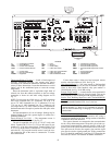
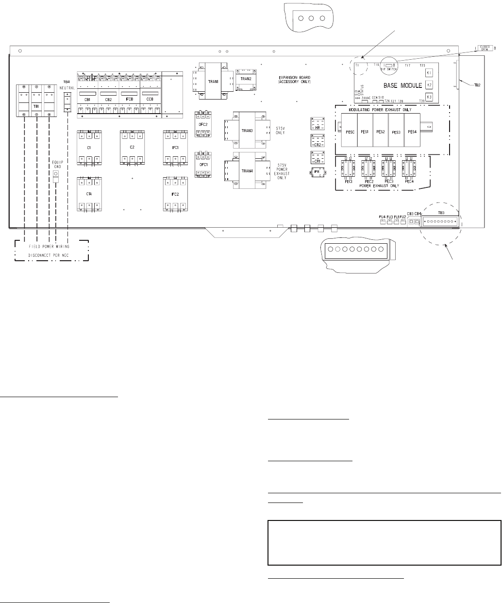
SEE DETAIL B
R Y1 Y2 W1 W2 G C X
DETAIL A
(THERMOSTAT CONNECTION
LOCATION)
TB3
SEE DETAIL A
DETAIL B
(SENSOR CONNECTION
LOCATION)
TI
T2
T3
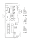
LEGEND
C—Compressor/Contactor FU — Fuse OFC — Outdoor-Fan Contactor
CB — Circuit Breaker GND — Ground PEC — Power Exhaust Controller
CCB — Control Circuit Breaker HR — Heater Relay PES — Power Exhaust Sequencer
CCN —
Carrier Comfort Network
IFC —
Indoor-Fan Circuit
PESC —
Power Exhaust Sequencer Control-
ler
CR — Control Relay IFCB — Indoor-Fan Circuit Breaker SIO — Serial Input/Output
DIP — Dual In-Line Package IFR — Indoor-Fan Relay TB — Terminal Block
EQUIP — Equipment NEC — National Electrical Code TRAN — Transformer