


95
Filter Drier —
Replace whenever refrigerant system is ex-
posed to atmosphere.
Protective Devices
COMPRESSOR PROTECTION
Overcurrent
— Each compressor has one manual reset, cali-
brated trip, magnetic circuit breaker. Do not bypass connec-
tions or increase the size of the circuit breaker to correct trou-
ble. Determine the cause and correct it before resetting the
breaker.
Overtemperature
— Each 06D type compressor (48AJ,AK,
AW,AY020-035 and 48EJ,EK,EW,EY024-038 units only) has
an internal protector to protect it against excessively high dis-
charge gas temperatures.
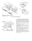
Crankcase Heater
— Each compressor has a crankcase heater
to prevent absorption of liquid refrigerant by oil in the crank-
case when the compressor is idle. Since power for the crank-
case heaters is drawn from the unit incoming power, main unit
power must be on for the heaters to be energized.
EVAPORATOR FAN MOTOR PROTECTION — A manu-
al reset, calibrated trip, magnetic circuit breaker protects
against overcurrent. Do not bypass connections or increase the
size of the breaker to correct trouble. Determine the cause and
correct it before resetting the breaker. If the evaporator-fan
motor is replaced with a different horsepower motor, resizing
of the circuit breaker is required. Contact Carrier Application
Engineering.
CONDENSER-FAN MOTOR PROTECTION — Each
condenser-fan motor is internally protected against
overtemperature.
HIGH- AND LOW-PRESSURE SWITCHES — If either
switch trips, or if the compressor overtemperature switch
activates, that refrigerant circuit will be automatically
locked out. See Compressor Lockout Logic section on this
page.
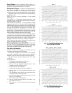
FREEZE PROTECTION THERMOSTAT (FPT) — Freeze
protection thermostats are located on the evaporator coil for
each circuit. One is located at the top and bottom of each coil. It
detects frost build-up and turns off the compressor, allowing
the coil to clear. Once the frost has melted, the compressor can
be reenergized.
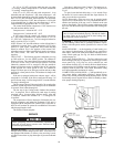
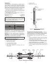
Relief Devices —
All units have relief devices to protect
against damage from excessive pressures (i.e., fire). These de-
vices are installed on the suction line, liquid line, and on the
compressor.
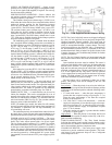
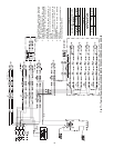
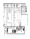
Power Circuit —
A typical power wiring schematic is
shown in Fig. 77.
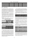
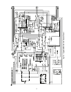
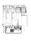
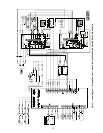
Control Circuit, 24-V —
This control circuit is protect-
ed against overcurrent by a 3.2 amp circuit breaker (CB4).
Breaker can be reset. If it trips, determine cause of trouble be-
fore resetting. A typical 24-v control wiring schematic is
shown in Fig. 78 and 79.
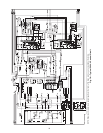
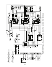
Control Circuit, 115-V —
This control circuit is pro-
tected against overcurrent by a 5.2 amp circuit breaker (CB3).
Breaker can be reset. If it trips, determine cause of trouble be-
fore resetting. A typical 115-v control wiring schematic is
shown in Fig. 80 and 81.
Compressor Lockout Logic —
If any of the safeties
trip, the circuit will automatically reset (providing the safety
has reset) and restart the compressor in 15 minutes. If any of
the safeties trip 3 times within a 90-minute period, then the cir-
cuit will be locked out and will require manual resetting by
turning off either the unit disconnect or the control circuit
breaker, or opening the thermostat.
If the compressors have bee off for more than 15 minutes
and the outdoor-air temperature (OAT) is less than 45 F then
safeties will be ignored for 5 minutes.
Replacement Parts —
A complete list of replacement
parts may be obtained from any Carrier distributor upon
request.
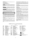
LEGEND for Fig. 77-83 — Typical Wiring Schematics
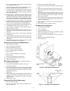
IMPORTANT: After a prolonged shutdown or service job,
energize the crankcase heaters for 24 hours before starting
the compressors.
AFS —
Airflow Switch
AHA —
Adjustable Heat Anticipator
BP —
Building Pressure
BR —
Burner Relay
C —
Contactor, Compressor
CAP —
Capacitor
CB —
Circuit Breaker
CC —
Cooling Compensator
CCB —
Controller Circuit Breaker
CCH —
Crankcase Heater
CLSASP —
Cooling Supply Air
Set Point Potentiometer
COM —
Communication
COMP —
Compressor Motor
CR —
Control Relay
CV —
Constant Volume
DM —
Damper Motor
DP —
Duct Pressure
EC —
Enthalpy Control
FLA —
Full Load Amps
FPT —
Freeze Protection Thermostat
FU —
Fuse
GVR —
Gas Valve Relay
HPS —
High-Pressure Switch
HS —
Hall Effect Sensor
HTSASP—
Heating Supply Air Set Point
Potentiometer
HV —
High Voltage
IDM —
Induced-Draft Motor
IFC —
Indoor Fan Contactor
IFCB —
Indoor Fan Circuit Breaker
IFM —
Indoor-Fan Motor
IFR —
Indoor-Fan Relay
IGC —
Integrated Gas Unit Controller
IP —
Internal Protector
L —
Light
LPS —
Low-Pressure Switch
LS —
Limit Switch
MGV —
Main Gas Valve
NC —
Normally Closed
NO —
Normally Open
OAT —
Outdoor-Air Thermostat
OD —
Outdoor
OFC —
Outdoor-Fan Contactor
OFM —
Outdoor-Fan Motor
PEC —
Power Exhaust Contactor
PEM —
Power Exhaust Motor
PES —
Power Exhaust Sequencer
PESC —
Power Exhaust Sequencer Controller
PL —
Plug Assembly
LEGEND
RAT —
Return-Air Thermistor
RS —
Rollout Switch
SAT —
Supply-Air Thermostat
SEN —
Sensor
SW —
Switch
TB —
Terminal Block
TC —
Thermostat, Cooling
TH —
Thermostat, Heating
TRAN —
Transformer
UL —
Compressor Unloader
VFD —
Variable Frequency Drive
Terminal (Marked)
Terminal (Unmarked)
Terminal Block
Splice
Factory Wiring
Field Wiring
To indicate common potential only.
Not to represent wiring.