


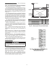
51
ECONOMIZER SETTINGS
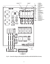
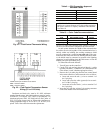
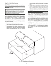
Accessory Enthalpy Control (Fig. 46)
— The control
(HH57AC077) is mounted in the economizer hood. See
Fig. 37. The enthalpy setting adjustment is on the enthalpy con-
trol. For maximum benefit of outdoor air, set enthalpy control
to A. See Fig. 47 and 48.
The enthalpy controls operation of the economizer outdoor-
air damper to provide free cooling on a signal form the cooling
thermostat.
Enthalpy Control Installation
— The outdoor air enthalpy
control is installed on the inside panel of the outdoor air hood.
The enthalpy control should be mounted when the outdoor air
hoods are assembled. To install the control, perform the follow-
ing procedure:
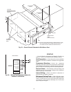
1. Turn off all power. Ensure disconnect is locked out.
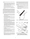
2. Remove the economizer inlet filters from the bottom of
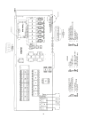
the right hand economizer hood. See Fig. 37. See Fig. 49
for economizer details.
3. Mount the outdoor air enthalpy sensor inside the right
economizer hood on the right side panel of the hood, ad-
jacent to the outdoor-air thermistor.
4. Locate the red, violet, and brown wires near the outdoor
air thermistor. Remove the splice from the red and violet
wires. Remove the cap from the brown wire.
5. Install a
1
/
4
-in. push on terminal (field-supplied) on the vi-
olet and brown wires.
6. Connect a
1
/
4
-in. push on terminal (field-provided) to one
end of a 18-gage, 6-in. jumper wire (field-provided).
Connect the other end to the red wire and attach a
1
/
4
-in.
push on connector (field-provided).
7. Connect the red wire with the jumper to terminal TR1.
Connect the jumper to terminal 2. Connect the brown wire
to terminal TR. Connect the violet wire to terminal 3. All
connections are on the enthalpy control.
8. Replace the economizer filters.
9. Return power to unit.
Accessory Differential Enthalpy Control (Fig. 46)
— The
control (HH57AC077), in conjunction with the accessory en-
thalpy sensor (HH57AC078), controls economizer operation
according to the differential enthalpy. The control is mounted
in the economizer hood. The sensor is mounted in the return
duct (48AJ,AK and 48EJ,EK) or return air plenum (48AW,AY
and 48EW,EY).
Differential Enthalpy Sensor Installation
— To install the
control, perform the following procedure:
1. Turn off all power. Ensure disconnect is locked out.
2. Remove the economizer inlet filters from the bottom of
the right hand economizer hood. See Fig. 37 and 49.
3. Remove the factory-installed, 620-ohm jumper between
terminals SR and + on the enthalpy control located inside
the outdoor air hood.
4. Connect the violet wire from the enthalpy sensor kit to
the + terminal on the enthalpy control. Connect the blue
wire from the enthalpy sensor kit to the SR terminal on
the enthalpy control.
5. Turn the enthalpy control set point potentiometer clock-
wise past the ‘‘D’’ setting on the enthalpy control to con-
figure the control to operate on differential enthalpy. See
Fig. 47.
6. Remove the return-air enthalpy sensor from the accessory
package. Using the screws provided, mount the sensor in-
side the return duct near the unit. Do not locate the control
too far from the unit, or the wires will not reach from the
sensor to the control. On 48AW,AY and 48EW,EY units,
the enthalpy sensor can be installed in the return air sec-
tion of the unit, under the return air dampers.
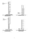
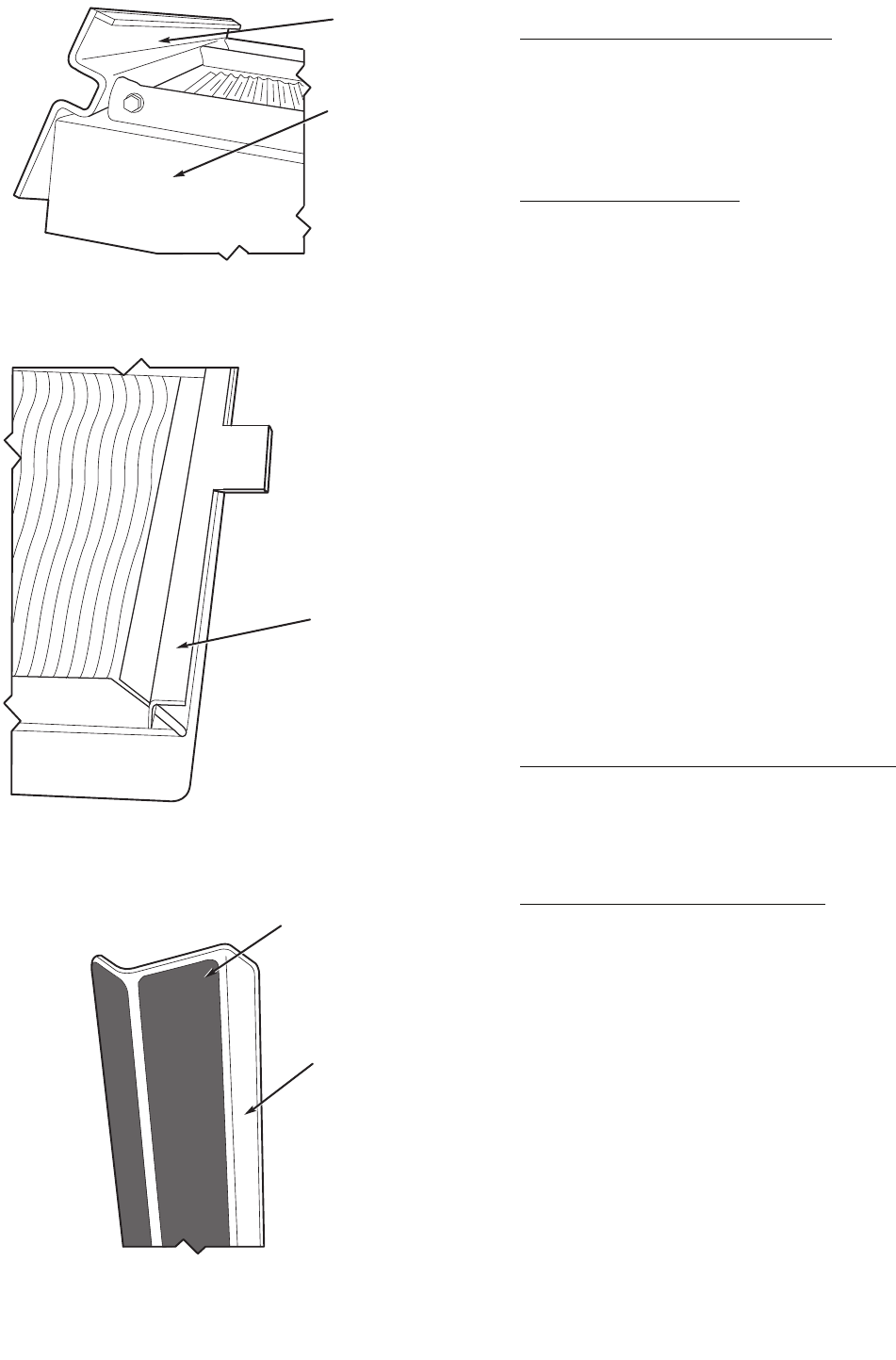
MOUNTING ANG
L
(WITHOUT TABS)
FILTER TRACK
ASSEMBLY
BLACK SEAL STRIP
(CENTERED)
FILTER COVER
MOUNTING ANGLE
(WITH TABS)
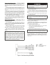
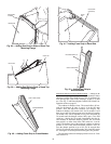
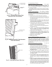
Fig. 43 — Mounting Angle (Without Tabs)
Attached to Filter Track Assembly
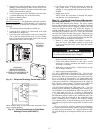
Fig. 44 — Mounting Angle (With Tabs) Attached to
Filter Track Assembly
Fig. 45 — Attaching Seal Strip to Filter Cover