


80
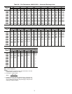
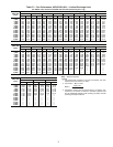
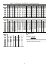
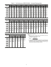
Return-Air Filters — Check that correct filters are in-
stalled in filter tracks (see Tables 1A and 1B). Do not operate
unit without return-air filters.
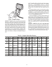
Filter Replacement — To replace filters, open filter ac-
cess door (marked with label). Remove inner access panel. Re-
move plastic filter retainer in between filter tracks by sliding
and pulling outward. Remove first filter by sliding it out of the
opening in filter track. Locate filter removal tool, which is
shipped next to the return air dampers. Use the filter removal
tool to remove the rest of the filters.
Outdoor-Air Inlet Screens — Outdoor-air inlet screens
must be in place before operating unit.
Economizer Adjustment — Remove filter access
panel. Check that outdoor-air damper is closed and return-air
damper is open.
Economizer operation and adjustment are described in
Sequence of Operation section on this page; and Step 10 —
Make Outdoor Air Inlet Adjustments section on page 48.
Gas Heat — Verify gas pressures before turning on heat as
follows:
1. Turn off field-supplied manual gas stop, located external
to unit.
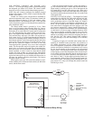
2. Connect pressure gage to supply gas tap, located on field-
supplied manual shutoff valve (see Fig. 23 on page 29).
3. Connect pressure gage to manifold pressure tap on unit
gas valve.
4. Supply gas pressure must not exceed 13.5 in. wg. Check
pressure at field-supplied shut-off valve.
5. Turn on manual gas stop and initiate a heating demand.
Jumper R to W1 in the control box to initiate heat. On
VAV units, the RAT (return-air temperature) must be less
than or equal to 68 F for heating to be energized.
6. Use the field test procedure to verify heat operation.
7. After the unit has run for several minutes, verify that in-
coming pressure is 6.0 in. wg or greater, and that the man-
ifold pressure is 3.5 in. wg. If manifold pressure must be
adjusted refer to Gas Valve Adjustment section on
page 93.
Sequence of Operation
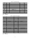
NOTE: Unit is shipped with default values that can be changed
through Service Tool, Building Supervisor, or Comfort-
WORKS® software or using an accessory Remote Enhanced
Display. See Table 35 for default values.
COOLING, CONSTANT VOLUME (CV) UNITS — On
power up, the control module will activate the initialization
software of the control board. The initialization software then
reads DIP switch no. 1 position to determine CV or VAV oper-
ation. Next, DIP switch no. 2 is read to determine if the control
is thermostat or sensor type operation. If switch 2 is open, then
sensors are employed. If switch no. 2 is closed, thermostat is
employed. Initialization sequence clears all alarms and alerts,
remaps the input/output database for CV operation, sets maxi-
mum heat stages to 2, and sets maximum cool stages to 3. The
control module reads DIP switch no. 3 and determines if the
unit will use expansion board operation.
The first time power is sent to the control board after a
power outage, power up takes 5 minutes plus a random 1 to
63 seconds.
The TSTAT function performs a thermostat based control
by monitoring Y1, Y2, W1, W2, and G inputs. These functions
control stages cool1, cool2, heat1, heat2, and indoor fan, re-
spectively. If TSTAT function is NOT selected, the control de-
termines the occupancy state on the Time Schedules or with re-
mote occupied/unoccupied input. If Temperature Compensated
Start is active, the unit will be controlled as in the Occupied
mode. User-defined set points are shown in Table 35.
Table 36 lists the software link points addressable by
DataPort™ and DataLINK™, Carrier devices that allow ac-
cess to unit control by non-Carrier energy management sys-
tems (EMS).
The occupied or unoccupied comfort set points must be se-
lected and the space temperature offset input will be used, if
present. The Occupied Heat set point default value is 68 F. The
Occupied Cool set point default value is 78 F. The Unoccupied
Heat set point default value is 55 F. The Unoccupied Cool set
point value is 90 F. The control board will set appropriate oper-
ating mode and fan control. The control board will turn on in-
door fan, if in Occupied mode, or determine if unit is in Unoc-
cupied mode and the space temperature is outside of the unoc-
cupied comfort set points, (Unoccupied Heat or Unoccupied
Cool).
The control board will then monitor space temperature
against comfort set points and control heating or cooling stages
as required. If system is in the Occupied mode, the economizer
will operate as required. If the system is in Unoccupied mode,
the system will perform nighttime free cool and IAQ (indoor
air quality) pre-occupancy purge as required (when functions
are enabled via software). Whenever the DX (direct expansion)
cooling is requested, the outdoor fan will operate.
The control board will operate economizer, run diagnostics
to monitor alarms/alerts at all times, and respond to CCN com-
munications to perform any configured network POC (product
outboard control) functions such as time and outdoor-air tem-
perature broadcast and Global occupancy broadcast. When the
optional expansion I/O board is employed, it will: perform pe-
riodic scan and maintain database of expanded I/O points, per-
form Fire/Smoke control (power exhaust required); and if in
Occupied mode perform IAQ control and monitor fan, filter,
demand limit, and field-applied status (with accessories).
If thermostats are used to energize the G input, the control
will turn on indoor fan without delay and open economizer
dampers to minimum position. If thermostats are used to deen-
ergize the G input, the control board will turn off indoor fan
without any delay and close economizer dampers.
When cooling, G must be energized before cooling can op-
erate. The control board determines if outdoor conditions are
suitable for economizer cooling using the standard outdoor air
thermistor. For economizer to function for free cooling, the en-
thalpy must be low, the outdoor air must equal to or less than
the High Outdoor Air Temperature Lockout (default is 65 F),
the SAT (supply-air temperature) thermistor is NOT in alarm,
and outdoor air reading is available. When these conditions are
satisfied, the control board will use economizer as the first
stage of cooling.
When Y1 input is energized, the economizer will be modu-
lated to maintain SAT at the defined set point. The default is
55 F. When SAT is above the set point, the economizer will be
100% open. When SAT is below the set point, the economizer
will modulate between minimum and 100% open position.
When Y2 is energized, the control module will turn on com-
pressor no. 1 and continue to modulate economizer as de-
scribed above. If the Y2 remains energized and the SAT read-
ing remains above the set point for 15 minutes, compressor
no. 2 will turn on. If Y2 is deenergized at any time, only the last
stage of compression that was energized will be turned off. If
outdoor conditions are not suitable for economizer cooling, the
economizer will go to minimum position and cycle compressor
no. 1 and 2 based on demand from Y1 and Y2 respectively.
The compressors will be locked out when the SAT temperature
is too low (less than 40 F for compressor no. 1 and less than
45 F for compressor no. 2.) After a compressor is locked out, it
can restart after normal time guard period.