


47
Conductors and drain wire must be 20 AWG minimum
stranded, tinned copper. Individual conductors must be insulat-
ed with PVC, PVC/nylon, vinyl, Teflon, or polyethylene. An
aluminum/polyester 100% foil shield and an outer jacket of
PVC, PVC/nylon, chrome vinyl, or Teflon with a minimum op-
erating temperature range of -20 C to 60 C (-4 F to 140 F) is re-
quired. Table 9 lists cables that meet the requirements.
Table 9 — CCN Connection Approved
Shielded Cables
Table 10 — Color Code Recommendations
NOTE: If a cable with a different color scheme is selected, a
similar color code should be adopted for the entire network.
At each system element, the shields of the communication
bus cables must be tied together. If the communication bus is
entirely within one building, the resulting continuous shield
must be connected to a ground at one point only. If the com-
munication bus cable exits from one building and enters anoth-
er, the shields must be connected to grounds at the lightning
suppressor in each building where the cable enters or exits the
building (one point per building only).
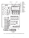
To connect the unit to the network:
1. Turn off power to the control box.
2. Cut the CCN wire and strip the ends of the red (+), white
(ground), and black (-) conductors. (If a different network
color scheme is used, substitute appropriate colors.)
3. Remove the 3-pin male plug from the base control board
in the main control box, and connect the wires as follows:
a. Insert and secure the red (+) wire to terminal 1 of
the 3-pin plug.
b. Insert and secure the white (ground) wire to termi-
nal 2 of the 3-pin plug.
c. Insert and secure the black (-) wire to terminal 3 of
the 3-pin plug.
4. Insert the plug into the existing 3-pin mating connector
on the base module in the main control box.
MANUFACTURER CABLE PART NO.
Alpha 2413 or 5463
American A22503
Belden 8772
Columbia 02525
IMPORTANT: When connecting the CCN communica-
tion bus to a system element, use a color coding system for
the entire network to simplify installation and checkout.
See Table 10.
SIGNAL
TYPE
CCN BUS CONDUCTOR
INSULATION COLOR
CCN PLUG
PIN NO.
Positive (+) RED 1
Ground WHITE 2
Negative (-) BLACK 3
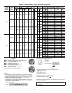
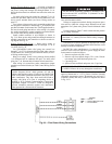
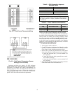
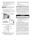
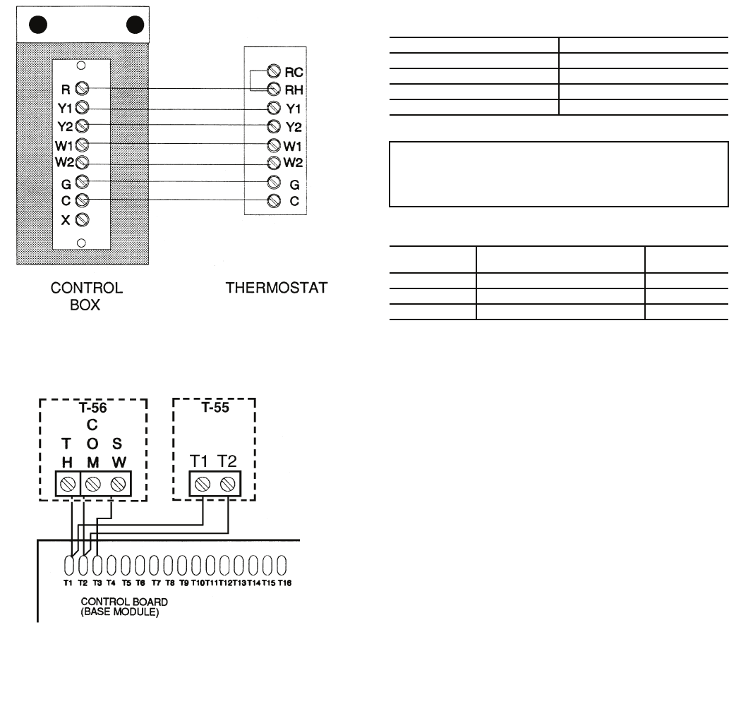
Fig. 32 — Field Control Thermostat Wiring
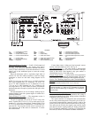
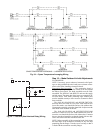
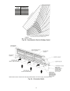
NOTE: Sensor part numbers are as follows:
T-55 — CEC0121448-01
T-56 — CEC0121448-01
Fig. 33 — Field Control Temperature Sensor
Wiring (CV or VAV Units)