


86
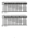
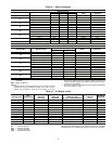
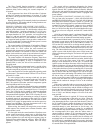
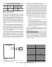
Table 40 — Occupied Heat and Morning Warm-Up
Operation and Controlling Factors
LEGEND
SPACE TEMPERATURE SENSOR CONTROL — If the unit
is equipped with a field-supplied space sensor and a remote
start/stop switch, constant volume (CV) cooling will operate as
follows: Stage 1 cooling begins when there exists a 1.5° F
demand and ends when the demand returns back to 0.5° F.
Stage 2 cooling begins when there is a 2.0° F demand and will
continue until the demand returns 1.0° F. Stage 2 cannot be en-
ergized until a minimum of eight minutes of Stage 1 operation
or as long as stage 1 is making a reduction in the space temper-
ature trend. If the temperature trends stop improving but the
demand still exceeds 2.0° F, then Stage 2 cooling will be
energized.
When economizer operation is suitable, the control will use
economizer, as the first stage of cooling will bring on the com-
pressor 1 when Stage 2 demand is called for. If supply-air tem-
perature (SAT) remains above supply-air set point (SASP) for
15 minutes after energizing compressor 1, then compressor 2
shall be started. When Stage 2 is satisfied, the last stage of
compression shall be dropped. When Stage 1 is satisfied, the
control will drop all DX cooling.
If the unit is equipped with a field-supplied space sensor and
a remote start/stop switch, CV heating will operate as follows:
Stage 1 heating begins when there exists 1.5° F demand and
ends when the demand returns back to 0.5° F. Stage 2 heating
begins when there is a 2.0° F demand and will continue until
the demand returns to 1.0° F. Stage 2 cannot be energized until
a minimum of eight minutes of Stage 1 operation or as long as
Stage 1 is making an increase in the space temperature trend. If
the temperature trends stop improving but the demand still ex-
ceeds 2.0° F, then Stage 2 heating will be energized
SPACE TEMPERATURE RESET SENSOR (VAV Only) —
An accessory space temperature sensor (T-55 or T-56 without
offset) is required. Space temperature reset is used to reset the
supply-air temperature set point of a VAV system higher, as the
space temperature falls below the Occupied Cool set point. As
the space temperature falls below the Occupied Cool set point,
the supply-air temperature will be reset upward as a function of
the reset ratio. (Default is 3.) Reset ratio is expressed in degrees
change in supply-air temperature per degree of space tempera-
ture change. A reset limit will exist which will limit the maxi-
mum number of degrees the supply-air temperature may be
raised. (Default is 10 F.) Both the reset ratio and the reset limit
are user definable. The sequence of operation is as follows:
1. The on/off status of the unit supply fan is determined.
2. If the fan is ‘‘on,’’ the sequence will check if the system is
occupied.
3. If the system is in Occupied mode, the sequence will de-
termine if the reset option is enabled.
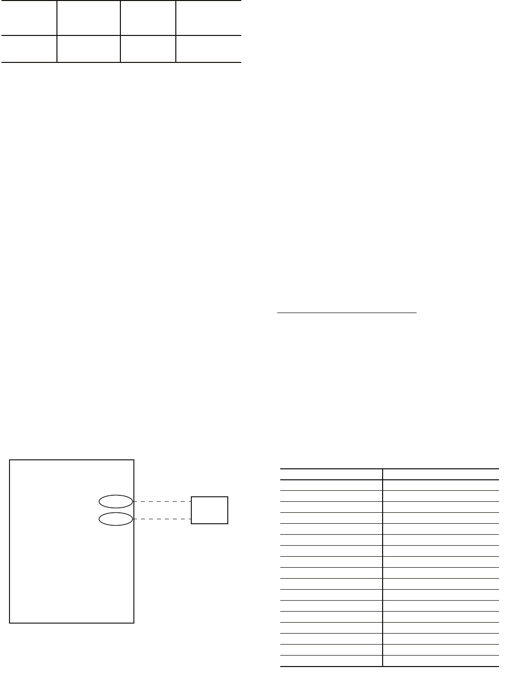
4. If the reset option is enabled, the sequence will read the
space temperature and compare it to the Occupied Cool
set point. If the temperature is below the Occupied Cool
set point, the algorithm will compute the reset value and
compare this value against the reset limit. If it is greater
than the reset limit, the sequence will use the reset limit as
the reset value. See Fig. 61.
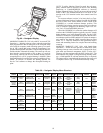
NOTE: A computer equipped with Carrier network access
software (ComfortWORKS®, Building Supervisor, or Service
Tool) or an accessory Remote Enhanced Display is required to
enable this function.
Space Temperature Reset Example
— The occupied cooling
set point is set to 73 F. The Reset Ratio is set to 5. The Reset
Limit is set to 20 F. The Reset Ratio determines how many de-
grees F the temperature is reset. At 72 F, the supply tempera-
ture will be reset 5 degrees higher. At 71 F, the supply tempera-
ture will be reset 10 degrees higher. At 70 F, the supply temper-
ature will be reset 15 degrees higher. At 69 F, the supply
temperature will be reset 20 degrees higher and the Reset Limit
will have been reached.
SOFTWARE
VERSION
OCCUPIED
HEAT
ENABLED
VIA
MORNING
WARM-UP
MAY START
DURING
TEMPERATURE
CONDITION
FOR HEAT
TO START
3.0 and Later DIP switch no. 5
Smart start or
within
10 minutes
RAT < OHSP
OHSP — Occupied Heat Set Point
RAT — Return-Air Temperature
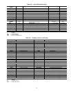
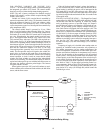
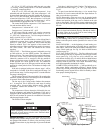
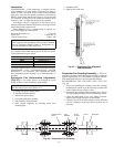
BASE MODULE
CONTROL BOARD
(+) T11
(-) T12
4-20 mA
INPUT
FIELD
SUPPLIED
INPUT DEVICE
Fig. 61 — Space Temperature Reset Wiring
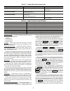
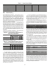
mA INPUT DEG. F RESET
4 0.00
5 1.25
6 2.50
7 3.75
8 5.00
9 6.25
10 7.50
11 8.75
12 10.00
13 11.25
14 12.50
15 13.75
16 15.00
17 16.25
18 17.50
19 18.75
20 20.00
LEGEND
T — Terminal
NOTE: The 4 to 20 mA input is a field-supplied non-Carrier EMS
(Energy Management System) device.