


2
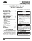
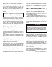
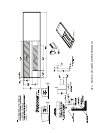
ROOF CURB — For vertical discharge units, assemble or in-
stall accessory roof curb in accordance with instructions
shipped with this accessory. See Fig. 1-4. Install insulation,
cant strips, roofing, and counter flashing as shown. Ductwork
can be installed to roof curb before unit is set in place. Curb
should be level. This is necessary to permit unit drain to func-
tion properly. Unit leveling tolerance is shown in Fig. 1-3.
Refer to Accessory Roof Curb Installation Instructions for
additional information as required. When accessory roof curb
is used, unit may be installed on class A, B, or C roof covering
material.
ALTERNATE UNIT SUPPORT — When the preferred curb
or slab mount cannot be used, support unit with sleepers on pe-
rimeter, using unit curb support area. If sleepers cannot be
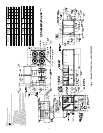
used, support long sides of unit (refer to Fig. 5-16) with a mini-
mum number of 4-in. x 4-in. pads spaced as follows:
48AJ,AK,AW,AY020-030 and 48EJ,EK,EW,EY024-034 units
require 3 pads on each side; 48AJ,AK,AW,AY035-050 and
48EJ,EK,EW,EY038-048 units require 4 pads on each side;
48AJ,AK,AW,AY060 and 48EJ,EK,EW,EY054-068 units re-
quire 6 pads on each side. Unit may sag if supported by corners
only.
Step 2 — Rig and Place Unit — Inspect unit for
transportation damage. See Tables 1A and 1B for physical data.
File any claim with transportation agency.
Do not drop unit; keep upright. Use spreader bars over unit
to prevent sling or cable damage. Level by using unit frame as
a reference; leveling tolerance is shown in Fig. 1-3. See Fig. 17
for additional information. Unit operating weight is shown in
Table 2.
NOTE: On retrofit jobs, ductwork may be attached to old unit
instead of roof curb. Be careful not to damage ductwork when
removing old unit. Attach existing ductwork to roof curb
instead of unit.
Four lifting lugs are provided on the unit base rails as shown
in Fig. 5-16. Refer to rigging instructions on unit.
POSITIONING — Maintain clearance, per Fig. 5-16, around
and above unit to provide minimum distance from combustible
materials, proper airflow, and service access.
Do not install unit in an indoor location. Do not locate unit
air inlets near exhaust vents or other sources of contaminated
air. For proper unit operation, adequate combustion and venti-
lation air must be provided in accordance with Section 5.3 (Air
for Combustion and Ventilation) of the National Fuel Gas
Code, ANSI Z223.1 (American National Standards Institute).
Although unit is weatherproof, guard against water from
higher level runoff and overhangs.
Locate mechanical draft system flue assembly at least 4 ft
from any opening through which combustion products could
enter the building, and at least 4 ft from any adjacent building.
When unit is located adjacent to public walkways, flue assem-
bly must be at least 7 ft above grade.
ROOF MOUNT — Check building codes for weight distribu-
tion requirements. See Fig. 17. Unit operating weight is shown
in Table 2.
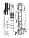
Step 3 — Field Fabricate Ductwork — Secure all
ducts to building structure. Use flexible duct connectors be-
tween unit and ducts as required. Insulate and weatherproof all
external ductwork, joints, and roof openings with counter
flashing and mastic in accordance with applicable codes.
NOTE: Due to width of the horizontal supply/return ductwork,
provisions should be made for servicing of the outdoor air fil-
ters (i.e., catwalk over ductwork).
Ducts passing through an unconditioned space must be in-
sulated and covered with a vapor barrier. Outlet grilles must not
lie directly below unit discharge. The return duct must have a
90-degree elbow before opening into the building space if the
unit is equipped with power exhaust.
To attach ductwork to roof curb, insert duct approximately
10 to 11 in. up into roof curb. Connect ductwork to 14-gage
roof curb material with sheet metal screws driven from inside
the duct.
Step 4 — Make Unit Duct Connections
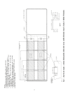
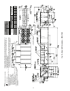
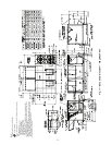
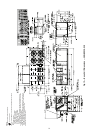
48AJ,AK,EJ,EK UNITS — Unit is shipped for through-the-
bottom duct connections. Field-fabricated ductwork should be
attached to the roof curb. Supply and return duct dimensions
are shown in Fig. 5-7 and 11-13. Air distribution is shown in
Fig. 18 and 19. Refer to installation instructions shipped with
roof curb for more information.
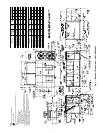
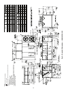
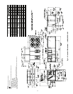
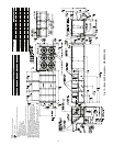
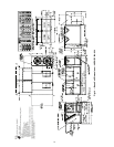
48AW,AY,EW,EY UNITS — Remove shipping covers from
supply and return air openings. Attach field-supplied ductwork
to unit. Connect to the unit with a single duct for all supply
openings and with a single duct for all return openings. Split-
ting of the airflow into branch ducts should not be done at the
unit. Sufficient duct length should be used prior to branching to
ensure the air temperatures are well mixed within the duct-
work. See Fig. 8-10 and 14-16 for duct opening dimensions.
Secure all ducts to building structure. Air distribution is shown
in Fig. 8-10 and 14-16.
Install accessory barometric relief or power exhaust in the
field-fabricated return ductwork. Refer to Step 11 — Position
Power Exhaust/Barometric Relief Damper Hood section on
page 52 for more information.
Instructions continued on page 28.
IMPORTANT: The gasketing of the unit to the roof curb is
critical for a watertight seal. Install gasket with the roof
curb as shown in Fig. 1-3. Improperly applied gasket can
also result in air leaks and poor unit performance.
For vertical supply and return units, tools or parts could
drop into ductwork and cause an injury. Install a 90-degree
elbow turn in the supply and return ductwork between the
unit and the conditioned space. If a 90-degree elbow cannot
be installed, then a grille of sufficient strength and density
should be installed to prevent objects from falling into the
conditioned space.