


84
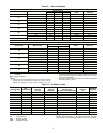
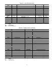
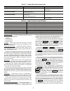
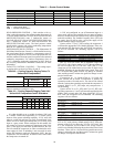
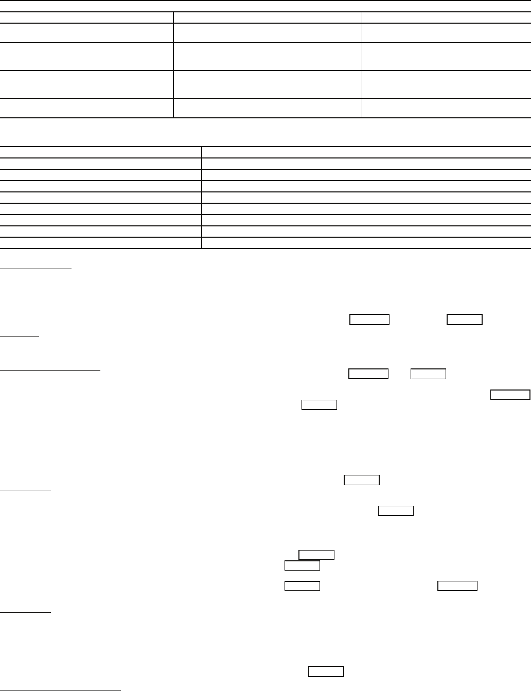
Table 37 — Staged Gas System Components
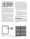
Table 38 — Stage Gas System Inputs/Outputs
Operating Modes
— The SGC will operate the unit in one of
the following operating modes:
• no mode
• Cooling Mode
• Heating1 Mode
• Heating2 Mode
No Mode
— In this mode, none of the heat stages are turned
on. No mode occurs if the Cool, Heat or Fan inputs are off or
the Cool input(s) are on.
Tempering (Cool) Mode
— In this mode, the SGC tempers in
incoming supply air to maintain the cooling supply air set
point. Tempering mode occurs if the Fan input is ON and all
Cool and Heat inputs are off.
When the SGC determines that the fan is on and the base
unit control is not calling for heat or mechanical cooling, the
SGC will stage heat to maintain the cooling set point which is
set on the CLSASP potentiometer of the SGC. This set point
should be slightly below the supply air set point of the base unit
VAV control. Note that the supply-air temperature will still be
in the “cooling range.”
Heat1 Mode
— Heat1 mode is used on VAV applications as
they have one heat stage on the base unit control. CV units
have two heat stages and will not operate under Heat1 mode.
In this mode, heat is staged to control supply air temperature
to HTSASP. Heat1 mode occurs only if Heat1 is ON and Heat2
is OFF and Cool1 and Cool2 are OFF.
When the base unit control calls for first stage of heat, the
SGC will stage heat to maintain the heating set point set on the
potentiometer of the SGC. The HIR will be energized to com-
mand the zone terminals to open to maintain minimum heating
airflow.
Heat2 Mode
— Heat2 mode is used on CV applications as
they have 2 heat stages on the base unit control. VAV units
have only 1 heat stage and will not operate under Heat2 mode.
In this mode, when the base unit calls for the second stage
of heat, the SGC will turn on all available heat stages. This
mode only occurs if Heat1 and Heat2 are ON and Cool1 and
Cool2 are OFF.
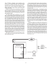
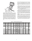
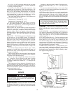
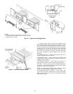
Accessory Navigator Display
— The Navigator Display is a
field-installed accessory. See Fig. 60. Navigator Display is to
be connected to LEN connections at communication board
which is attached to the heating and cooling supply air set point
potentiometers in heating section. The Navigator Display ac-
cessory is required for all units with staged gas control.
The display module provides the user interface to the Staged
Gas control system. See Fig. 60. The display has up and down
arrow keys, an key, and an key. These
keys are used to navigate through the different levels of the dis-
play structure. See Table 39. Press the ESCAPE key until the
display is blank to move through the top 11 mode levels indi-
cated by LEDs on the bottom left side of the display.
Pressing the and keys simultaneously
will scroll a text description across the display indicating the
full meaning of each display acronym. Pressing the
and keys when the display is blank (Mode LED lev-
el) will return the display to its default menu of rotating display
items. In addition, the password will be disabled requiring that
it be entered again before changes can be made to password
protected items.
When a specific item is located, the display will flash show-
ing the operator, the item, item value, and then the item units (if
any). Press the key to stop the display at the item val-
ue. Items in the Configuration and Service Test modes are
password protected. The display will flash PASS and WORD
when required. Use the and arrow keys to enter the 4
digits of the password. The default password is 1111.
Changing item values or testing outputs is accomplished in
the same manner. Locate and display the desired item. Press
the key to stop the display at the item value. Press the
key again so that the item value flashes. Use the ar-
row keys to change the value or state of an item and press the
key to accept it. Press the key and the
item, value, or units display will resume. Repeat the process as
required for other items.
The unit alarms can be cleared through Navigator display.
To check the current alarms, enter the Alarms menu. The first
submenu is the CRNT submenu. The CRNT function displays
the list of current alarms (maximum of 25). The second sub-
menu item is the RCRN (Reset All Current Alarms) function.
Press to reset the current alarms. The next submenu
item, HIST, displays the list of cleared alarms (maximum of
20). The HIST function can be cleared with the RHIS function.
ITEM FUNCTION LOCATION
Heating Controller (SGC) Logic and Output Relays Heating section
Supply-Air Thermistors (SAT) Sense unit leaving-air temperature Supply duct (factory-provided,
field-installed)
Cooling Supply Air Set Point
Potentiometer (CLSASP)
Specify set point for
tempering heat control
Set Point Range: 35 to 70 F
Heating section, next to SGC
Heating Supply Air Set Point
Potentiometer (HTSASP)
Specify set point for First-Stage
Heating control
Set Point Range: 80 to 125 F
Heating section, next to SGC
Air Flow Switch (AFS) Prove Supply Fan operation Fan supply air plenum
(factory-installed)
INPUT DESCRIPTION
Cool1 Relay in parallel with Compressor #1 contactor
Cool2 Relay in parallel with Compressor #2 contactor
Heat1 24V input from Base Unit control
Heat2 24V input from Base Unit control
Fan Air proving switch (contact closure on rise in static pressure)
Cool Supply Set Point Potentiometer, (range 35-70 F)
Heat Supply Set Point Potentiometer, (range 80-125 F)
Supply Air Thermistor (1, 2 and 3) Field-installed in supply ductwork (P/N HH79NZ016)
ESCAPE ENTER
ESCAPE ENTER
ESCAPE
ENTER
ENTER
ENTER
ENTER
ENTER
ENTER ESCAPE
ENTER