


49
Perform the following procedure to assemble the economiz-
er hood.
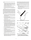
1. Apply black seal strip (provided in package) to outside
top-edge of hood sides. Wrap seal strip over edge to cover
top flange (6 hood sides). Make sure seal strip covers
screw holes. Allow strip to overhang
1
/
8
-in. past the end
opposite the mounting flange. See Fig. 36.
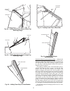
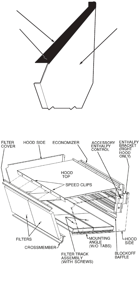
2. Assemble hood sides, top, and cross member with
gasketed screws provided. See Fig. 37.
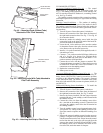
3. Attach 15 green speed clips (provided) to hood top.
4. Apply black seal strip (provided) to mounting flanges of
hood sides being sure to cover mounting holes. See
Fig. 38.
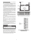
NOTE: Each hood assembly has one hood side with slots and
one hood side without slots. On the 48AJ,AK,AW,AY020-050
and 48EJ,EK,EW,EY024-048 units, the two outer hood assem-
blies must have the hood sides with the slots located adjacent
to each other when mounted on the unit. On the
48AJ,AK,AW,AY060 and 48EJ,EK,EW,EY054-068 units, the
two outer hood assemblies must have the hood sides with the
slots located adjacent to the center hood. The center hood
assembly should have hood side with slots located on the left
side.
5. Apply black seal strip (provided) to back of hood top
mounting flange. Seal strip of hood top mounting flange
must press tightly against seal strip of hood side mount-
ing flanges. See Fig. 39.
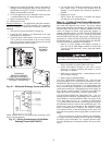
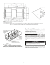
6. Add gray foam strip (provided in package) to cross mem-
bers on bottom tray. See Fig. 40.
7. Place gray foam strip (provided) on inside of slotted hood
side between filter and cross member opposite the mount-
ing end. See Fig. 41.
8. Attach gray foam strip (provided) to block-off baffle on
outer face of flange. See Fig. 42.
9. Remove the screws on each end and along top of damper
assembly of unit. Remove top 4 screws on each side of
filter panel under damper assembly. Set hood assembly in
place and attach to unit using these screws.
10. Attach the outside-air thermostat (OAT) that is supplied
from the factory or accessory field-supplied enthalpy sen-
sor onto the hood side furthest from the control box. The
OAT or enthalpy sensor is installed on the inside upper
right-hand corner using the mounting bracket and mount-
ing holes provided. Attach wiring to unit controls. If ac-
cessory enthalpy sensor is used, quick connects must be
attached to enthalpy sensor wires.
11. Remove screws along bottom of damper assembly. Lo-
cate and mount blockoff baffle using these screws.
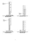
12. Assemble 2 filter tracks side-by-side with the assembled
ends together.
13. Attach mounting angle (without tabs) to the assembled
end of the filter track. See Fig. 43.
14. Attach 9 green speed clips (provided) to hood side panels
without slots. Engagement section of clip faces up and to-
wards the outside of the hood side panels.
15. Attach remaining mounting angle (with tabs) to other end
of the filter track with no. 10 screws provided. See
Fig. 44.
16. Place filter track assembly in bottom of hood by placing
tabbed end into slotted side (with tab on bottom) and
attaching opposite end to hood with speed clips and
gasketed screws provided. Tabs can be hand bent after
they have been inserted into the side.
NOTE: The filter track assembly end with screws should face
away from the other hood when mounted on the unit. Be sure
the filters are installed with the airflow in the correct direction.
NOTE: Tabs from both filter tracks will be in the same space.
After one filter track has been inserted into hood side, bend the
tabs so they will not interfere with installation of the second/
center hood.
17. Attach black seal strip (provided) to filter cover. Seal strip
should be applied centered over the holes of the one
flange, making sure to fully cover holes and centered over
the other large flange. See Fig. 45.
18. Slide two 20 x 25-in. filters into cross members of hood
assembly. Attach filter cover over filters with screws and
speed clips provided.
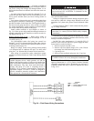
HOOD SIDE
TOP
FLANGE
SEAL
STRIP
BLACK
Fig. 36 — Adding Seal Strip to Top of Hood Sides
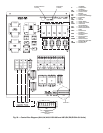
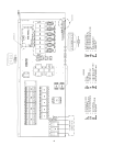
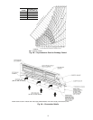
NOTE: Left side economizer hood has mounting angle without tabs
and filter rack assembled end on the opposite side.
Fig. 37 — Economizer Hood Assembly
(Right Side/Center Economizer Hood Shown)