


32
An electronic expansion board may be field-installed to pro-
vide the following features:
• provide discrete inputs for fan status, filter status, field-
applied status, and demand limit
• provide an output for the external alarm light indicator
• provide power exhaust fire outputs for direct control of
modulated power exhaust stages during fire or smoke
modes
• control of smoke control modes including evacuation,
smoke purge, pressurization, and fire shutdown (modu-
lating power exhaust required)
When the unit is connected to the CCN (Carrier Comfort
Network), the following expansion board features can be
utilized:
• perform Demand Limit functions based on CCN load-
shed commands or the state of the discrete input
• alarm monitoring of all key parameters
• CCN protocol
See Carrier TEMP or VVT® (Variable Volume and Tem-
perature) literature for complete TEMP (single zone) or VVT
(multi-zone) application information.
Features with Sensor Control of Unit (Network Applica-
tions) — The base control board provides, as standard, a con-
nection for use with a Carrier VVT system and can also be in-
tegrated into a Carrier Comfort Network.
When the unit is accessed via a PC equipped with
ComfortWORKS®, Building Supervisor, Service Tool soft-
ware, or accessory Remote Enhanced Display, the following
features can be accessed:
• on-board timeclock can be programmed
• occupancy schedules can be programmed
• unit set points can be changed
• alarms can be monitored
This access is available on the base control board via a
RJ-11 phone jack or a 3-wire connection to the communication
bus. See Fig. 27. The timeclock has a 10-hour minimum back-
up time to provide for unit power off for servicing unit or dur-
ing unexpected power outages. For complete Carrier Comfort
System (CCS) or Carrier Comfort Network (CCN) features
and benefits, refer to the product literature.
VARIABLE AIR VOLUME (VAV) APPLICATIONS
Features with Stand-Alone Applications
— The units, as
shipped, are operable as stand-alone units with the addition of a
timeclock to establish unit start and stop times.
Heating and cooling in both on and off modes is controlled
to default values by the base unit control. Set points may be
changed with appropriate input devices.
The control has an on-board occupancy schedule which can
be set using an input device and eliminates the need for an ex-
ternal timeclock.
During both the on and off periods, cooling operation is
controlled to the supply air setting and heating is controlled to
the return air setting (or to the optional space temperature sen-
sor). During the on period, the supply fan runs continuously.
During the off period, the supply fan will be activated if the re-
turn air sensor is outside of the set points and will run long
enough to accurately sample the space temperature. The supply
fan will then continue to run until any heating or cooling load is
satisfied, at which point it will turn off.
The use of a space sensor will allow for supply air reset to
conserve energy and maintain comfort. If equipped with an
override feature, the sensor will allow operation during the off
period for a fixed length of time.
Base unit control supports a Heat Interlock Relay (field sup-
plied) to fully open the VAV terminal devices during heating
operation.
Standard features of a VAV unit with a remote start/stop
switch are:
• control board diagnostics
• control of an outdoor condenser fan based upon outdoor
air temperature
• control of modulating economizer to provide free cool-
ing when outdoor conditions are suitable, using supply-
air temperature as a set point
• support of remote occupied/unoccupied input to start or
stop the unit
• provide power exhaust output to an external power
exhaust controller
• support supply-air temperature reset to offset supply air
set point
• support a field test for field check out
• support linkage to DAV (digital air volume) systems
• cooling capacity control of up to 6 stages plus econo-
mizer with compressors and unloaders to maintain sup-
ply air temperature set point during occupied periods
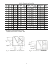
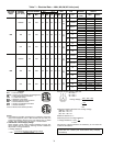
JUMPER CONNECTION
FOR VOLTAGE OUTPUT
JUMPER CONNECTION
FOR CURRENT OUTPUT
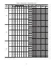
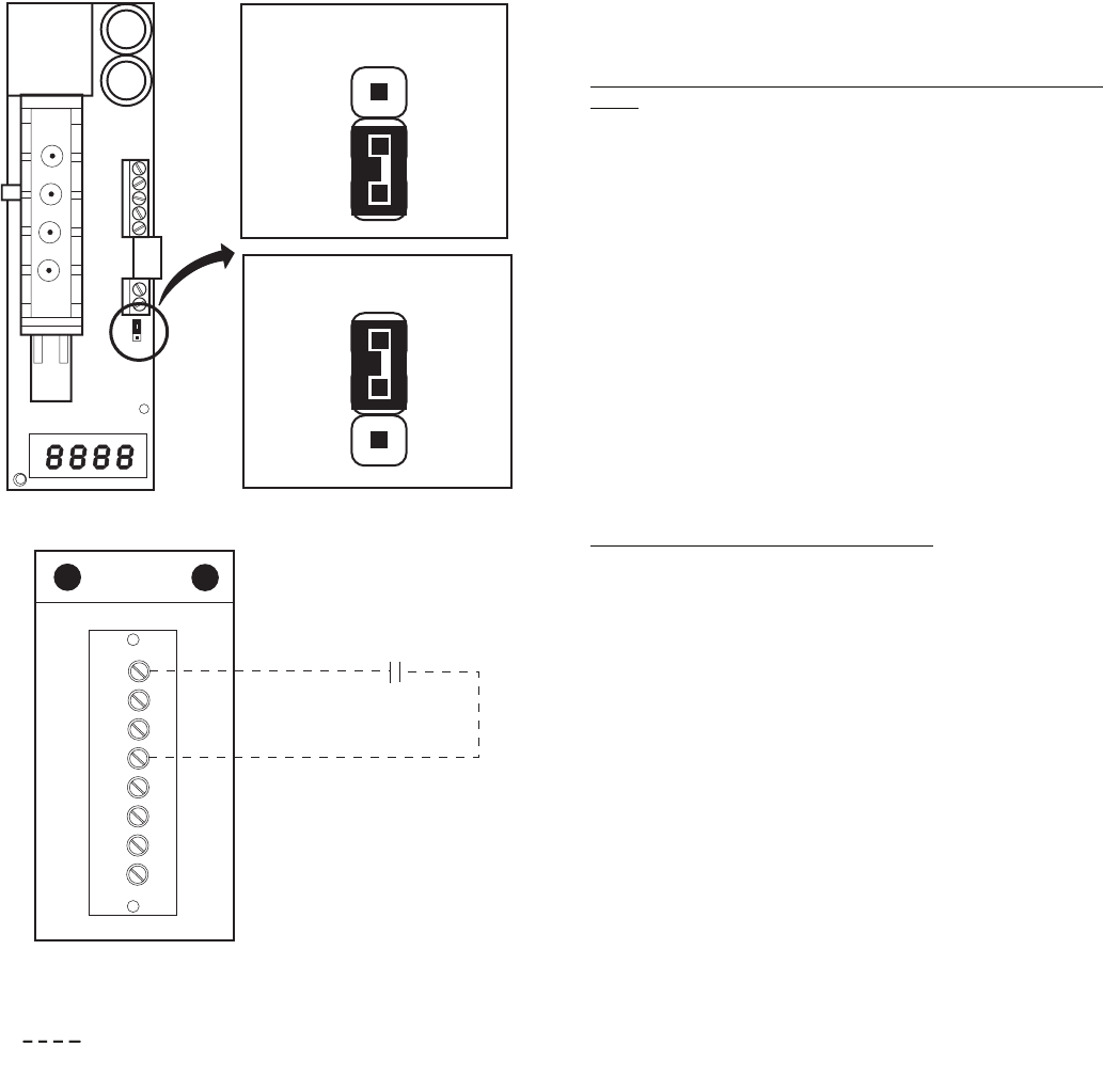
R
Y1
Y2
W1
W2
G
C
X
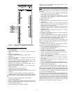
CONTROL
BOX
REMOTE
START/STOP
SWITCH
(FIELD-SUPPLIED)
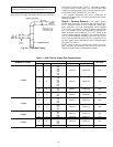
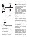
Fig. 25 — Indoor Air Quality Sensor Configuration
LEGEND
Fig. 26 — Field Control Remote Start/Stop
Field Supplied Wiring