


93
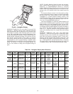
Power Failure — The economizer damper motor is a
spring return design. In event of power failure, dampers will re-
turn to fully closed position until power is restored.
Refrigerant Charge — Amount of refrigerant charge is
listed on unit nameplate and in Tables 1A and 1B. Refer to
Carrier GTAC II; Module 5; Charging, Recovery, Recycling,
and Reclamation section for charging methods and procedures.
Unit panels must be in place when unit is operating during
charging procedure.
NOTE: Do not use recycled refrigerant as it may contain
contaminants.
NO CHARGE — Use standard evacuating techniques. After
evacuating system, weigh in the specified amount of refriger-
ant (refer to Tables 1A and 1B).
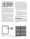
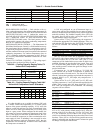
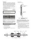
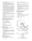
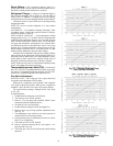
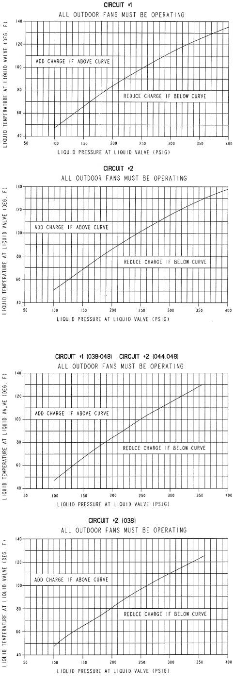
LOW CHARGE COOLING — Using appropriate cooling
charging chart (see Fig. 71-74), add or remove refrigerant until
conditions of the appropriate chart are met. Note that charging
chart is different from those normally used. An accurate pres-
sure gage and temperature sensing device are required. Mea-
sure liquid line pressure at the liquid line service valve using
pressure gage. Connect temperature sensing device to the liq-
uid line near the liquid line service valve and insulate it so that
outdoor ambient temperature does not affect reading.
Using the above temperature and pressure readings, find the
intersect point on the appropriate cooling charging chart. If in-
tersection point on chart is above line, add refrigerant. If inter-
section point on chart is below line, carefully reclaim some of
the charge. Recheck suction pressure as charge is adjusted.
NOTE: Indoor-air cfm must be within normal operating range
of unit. All outdoor fans must be operating.
Thermostatic Expansion Valve (TXV) — Each circuit
has a TXV. The TXV is nonadjustable and is factory set to main-
tain 10 to 13° F superheat leaving the evaporator coil. The TXV
controls flow of liquid refrigerant to the evaporator coils.
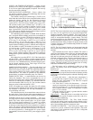
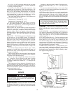
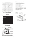
Gas Valve Adjustment
NATURAL GAS — The 2-stage gas valve opens and closes
in response to the thermostat or limit control.
When power is supplied to valve terminals 3 and 4, the pilot
valve opens to the preset position. When power is supplied to
terminals 1 and 2, the main valve opens to its preset position.
The regular factory setting is stamped on the valve body
(3.5 in. wg).
To adjust regulator:
1. Set thermostat at setting for no call for heat.
2. Turn main gas valve to OFF position.
3. Remove
1
/
8
-in. pipe plug from manifold. Install a water
manometer pressure-measuring device.
4. Set main gas valve to ON position.
5. Set thermostat at setting to call for heat (high fire).
6. Remove screw cap covering regulator adjustment screw
(See Fig. 75).
7. Turn adjustment screw clockwise to increase pressure or
counterclockwise to decrease pressure.
8. Once desired pressure is established, set unit to no call for
heat (3.3-in. wg high fire).
9. Turn main gas valve to OFF position.
10. Remove pressure-measuring device and replace
1
/
8
-in.
pipe plug and screw cap.
11. Turn main gas valve to ON position and check heating
operation.
Fig. 71 — Cooling Charging Chart,
48EJ,EK,EW,EY024-034
Fig. 72 — Cooling Charging Chart,
48EJ,EK,EW,EY038-048