


55
Install Motormaster® III Controls
— Only one Motormaster
III control is required per unit.
Motor — One outdoor-fan motor (OFM) must be changed out
in the field to accommodate the Motormaster III accessory.
The replacement motor part no. is HD52AK652.
For 48AJ,AK,AW,AY020-030 and 48EJ,EK,EW,EY024-
034 units, the Motormaster controlled OFM is the no. 2 OFM
and is located at the left side of the unit looking from the com-
pressor end. The no. 1 OFM is controlled to shut off at 55 F and
on at 65 F outdoor-air temperature and does NOT need to be
changed out.
For 48AJ,AK,AW,AY035-050 and 48EJ,EK,EW,EY038-
054 units, the Motormaster controlled OFM is no. 1 OFM and
is located at the left side of the unit looking from the compres-
sor end and the second motor back. The no. 3 and 4 OFM are
controlled to shut off at 55 F and on at 65 F outdoor-air temper-
ature and do NOT need to be changed out. The no. 2 OFM is
intended to run at all ambient temperatures.
For 48AJ,AK,AW,AY060 and 48EJ,EK,EW,EY058-068
units, the Motormaster controlled OFM is no. 3 OFM and is lo-
cated at the left side of the unit looking from the compressor
end and the second motor back.
The no. 4, 5, and 6 OFMs are controlled to shut off at 55 F
and on at 65 F outdoor-air temperature and do NOT need to be
changed out. The no. 1 and 2 OFMs are intended to run at all
ambient temperatures.
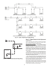
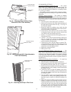
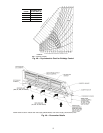
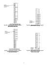
Sensor — Install the sensor for thermistor input control in the
location shown in Fig. 53A-53E. Connect sensor leads to the
violet and gray control signal leads on the Motormaster III
control.
Signal Selection Switch — Remove the cover of the Motor-
master III control. Set the switch to accept the thermistor
sensor input signal. Set the frequency to match the unit power
supply (60 Hz).
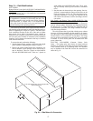
Motormaster III Control — The recommended mounting loca-
tion is in the indoor fan section, mounted on the panel that sep-
arates the indoor and outdoor sections. On VAV units, this
location is next to the VFD (variable frequency drive).
Do not route the Motormaster III control wiring next to the
VFD on VAV units. Use a separate connector through the parti-
tion when wiring to the OFM.
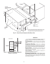
Electrical Connections
When replacing the OFM, reconnect the black, yellow, and
blue wires form the outdoor fan contactor to the black, yellow,
and blue wires of the Motormaster III control. Run new wires
from the red, orange, and brown wires to the leads of the new
OFM. Connect the green wire from the control to ground.
NOTE: On all 575-v units, 2 transformers (part no.
HT01AH851) must be used for each Motormaster III control
to lower the supply voltage to the control to 460-v. Transform-
ers can be mounted anywhere outside the control box.
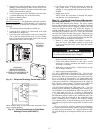
To avoid possibility of electrical shock and personal
injury, turn off all power to unit before making electrical
connections.
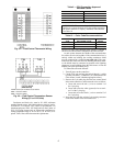
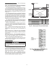
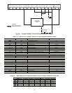
18
1
BOTH SIDES
CROSS-BREAK
0.5
61
4.62
17.167
BETWEEN
HOLES
(TYPICAL)
0.312 DIA
HOLES
B
A
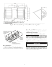
NOTE: All dimensions are in inches. Material: 20 gage galvanized
steel or other non-corrosive material.
Fig. 52 — Motormaster III Control Baffle Details
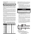
UNIT SIZE A B
48AJ,AK,AW,AY020-050 and
48EJ,EK,EW,EY024-054
80.5 79.5
48AJ,AK,AW,AY060 and
48EJ,EK,EW,EY058-068
120.5 119.5
Fig. 53A — Motormaster III Sensor Location
(48AJ,AK,AW,AY020-030 and
48EJ,EK,EW,EY024-034)