


33
• control of one stage of heat to maintain return-air tem-
perature at heating set point during occupied periods
• provide a variable frequency drive high voltage relay
output to enable VFD
• control of heat interlock relay
• IAQ (Indoor Air Quality) sensor
• OAQ (Outdoor Air Quality) sensor
• DX compressor lockout occurs at 45 F outdoor air tem-
perature and is factory-enabled on units with serial num-
ber 0600F or later. This feature may be disabled through
the use of a computer
• compressor Time Guard® override (power up, minimum
off and on times)
With the addition of a remote start/stop switch heating or
cooling is enabled during unoccupied periods as required to
maintain space temperature to within unoccupied set points.
Occupied heating is enabled or disabled by the position of
DIP (dual in-line package) switch no. 5.
Additional features may be provided with Electronic Ac-
cess to Unit Control Board. These features are:
• additional control board diagnostics
• electronic expansion board features (if installed)
• control of the economizer damper and indoor fan to
obtain unoccupied free cooling
• 365-day timeclock with backup (supports minute, hour,
day, month, and year)
• holiday table containing up to 18 holiday schedules
• occupancy control with 8 periods for unit operation
• support a set of display, maintenance, configuration, ser-
vice, and set point data tables for interface with Building
Supervisor, ComfortWORKS®, or Service Tool software
or accessory remote enhanced display
• CCN IAQ/OAQ (outdoor air quality) participation
When a VAV unit with a space temperature sensor is access-
ed via a computer, the following additional features are
available:
• ability to initiate timed override from T-55 sensors
• temperature compensated start to calculate early start
time before occupancy
• provide space temperature reset to reset the supply air set
point upward when the temperature falls below the occu-
pied cooling set point
An electronic expansion board may be field-installed to pro-
vide the following features:
• fan status
• filter status
• field-applied status
• demand limiting
• alarm light
• fire unit shutdown
• fire pressurization
• fire evacuation
• fire smoke purge
When the unit is connected to the CCN (Carrier Comfort
Network), the following features can be utilized:
• CCN demand limit participation
• modulated power exhaust override
• ability to use multiple space temperature sensors (multi-
ples of 4 and 9 only) to average space temperature (CV
and VAV only)
A field-supplied T-55 space temperature sensor can be add-
ed to monitor room temperature and provide unoccupied over-
ride capability (1 hour).
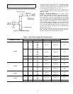
When the unit is equipped with a field-supplied space
temperature sensor and a remote contact closure (remote
start/stop) the occupied default set points will monitor unit
operation. The occupied default set points are 55 F (supply-air
temperature) cooling and 68 F (return-air temperature) heating.
See Fig. 26 for remote start/stop wiring.
NOTE: For units without a space temperature sensor and
which have not had the base unit control board accessed via
software to set an occupancy schedule, the remote start/stop
closure will allow the unit to operate in the pre-configured
occupied default set points of 55 F (supply-air temperature)
cooling and 68 F (return-air temperature) heating. Without an
occupancy schedule, the unit will control to the unoccupied
default set points of 90 F (return-air temperature) cooling and
55 F (return-air temperature) heating.
Features with Network Applications
— The base control
board provides, as standard, a connection for use with a Carrier
Comfort System and can also be integrated into a Carrier Com-
fort Network (CCN). When the unit is accessed via a PC
equipped with ComfortWORKS, Building Supervisor, or Ser-
vice Tool software or Remote Enhanced Display accessory, the
following features can be accessed:
• on-board timeclock can be programmed
• occupancy schedules can be programmed
• unit set points can be changed
• alarms can be monitored
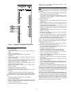
This access is available on the base control board via a
RJ-11 phone jack or a 3-wire connection to the communication
bus. See Fig. 27. The internal timeclock has a 10-hour mini-
mum back-up time to provide for unit power off for servicing
unit or during unexpected power outages. For complete Carrier
Comfort System (CCS) or Carrier Comfort Network (CCN)
features and benefits, refer to the product literature.
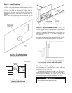
Step 9 — Make Electrical Connections
POWER WIRING — Units are factory wired for the voltage
shown on the unit nameplate.
When installing units, provide a disconnect per NEC
(National Electrical Code) of adequate size (MOCP [maximum
overcurrent protection] of unit is on the informative plate). All
field wiring must comply with NEC and all local codes and re-
quirements. Size wire based on MCA (minimum circuit amps)
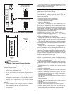
on the unit informative plate. See Fig. 28 for power wiring con-
nections to the unit power terminal block and equipment
ground.
The main power terminal block is suitable for use with alu-
minum or copper wire. See Fig. 28. Units have circuit breakers
for compressors, fan motors, and control circuit. If required by
local codes, provide an additional disconnect switch. Whenev-
er external electrical sources are used, unit must be electrically
grounded in accordance with local codes, or in absence of local
codes, with NEC, ANSI (American National Standards Insti-
tute) C1-latest year.
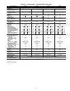
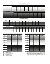
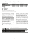
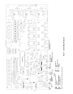
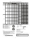
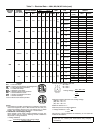
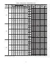
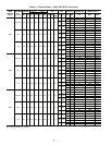
FIELD POWER SUPPLY — Unit is factory wired for volt-
age shown on unit nameplate. See Table 7 and 8 for electrical
data.
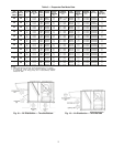
Field wiring can be brought into the unit from bottom
(through basepan and roof curb) or through side of unit (corner
post next to control box).
A 3
1
/
2
-in. NPT coupling for field power wiring and a
3
/
4
-in.
NPT coupling for 24-v control wiring are provided in basepan.
In the side post, there are two 2
1
/
2
-in. (48A020-030 and
48E024-034) or 3-in. (48A035-060 and 48E038-068) knock-
outs for the field power wiring. See Fig. 5-16. If control wiring
is to be brought in through the side of unit, a
7
/
8
-in. diameter
hole is provided in the condenser side post next to the control
box.
If disconnect box is mounted to corner post, be careful not
to drill any screws into the condenser coil.