


61
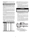
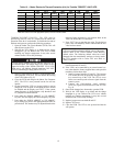
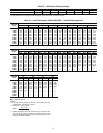
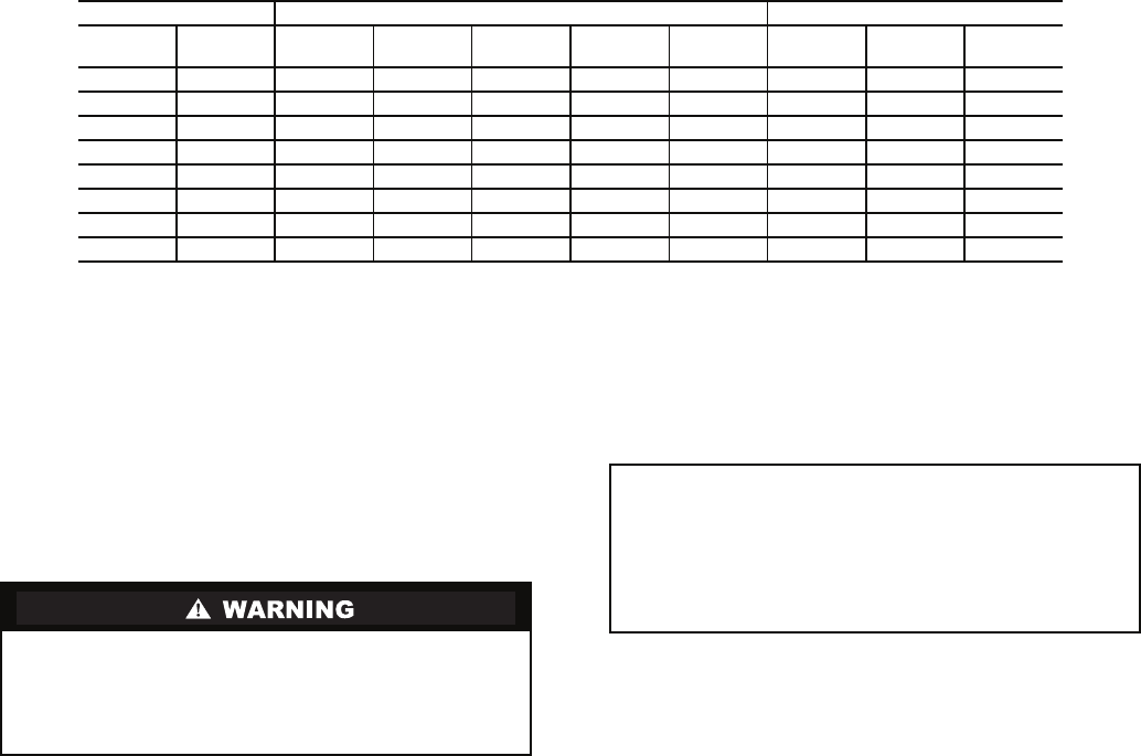
Table 13 — Motor Electronic Thermal Protection (tHr) for Toshiba TOSVERT 130-E3 VFD
*IFM Letter refers to the 15th digit (Motor Option) of the unit model number
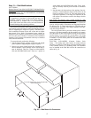
TOSHIBA TOSVERT VF-S9 VFD — The VFD must be
powered up, however, since it is located near the indoor fan,
operation of the fan is not desirable. To disable the fan and set
the duct static pressure, perform the following procedure:
1. Open the Indoor Fan Circuit Breaker (IFCB). This will
shut off power to the VFD.
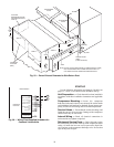
2. Wait for the VFD display to go blank and the charge
lamplight to go out. Remove the VFD cover without
touching any interior components. It may take several
minutes for the VFD to fully discharge.
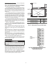
3. Remove jumper between R and CC on the terminal block
and replace the VFD cover. This will disable the running
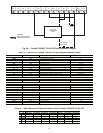
of the VFD. Refer to Fig. 58.
4. Close the IFCB and energize the Indoor Fan Contactor
(IFC). The VFD is now powered but the fan will not
operate.
5. On the front of the VFD is a keypad, which is used to
change the VFD set point. At this point the drive should
be disabled and the display read “OFF”. If the current
output frequency is displayed then verify that the R and
CC jumpers have been removed.
6. Press either the “DOWN ARROW” or “UP ARROW”
key once, this will display the current frequency set point.
7. Press either the “DOWN ARROW” or “UP ARROW”
key to change set point to the appropriate duct static set
point desired. This number may be adjusted based on the
amount of static pressure (in. wg) required. Refer to the
Table 8 to identify the VFD Set Point.
8. Press “ENT” key, to enter the new value. The desired set
point value will alternately flash to indicate that the new
value has been stored.
9. Fire-speed override mode is available by contact closure
between terminals S1 and CC.
10. If the VFD is to be controlled by an external control sys-
tem, other than the factory-supplied duct static pressure
transducer, follow these steps:
a. Install a jumper between S2 and CC. This jumper
will disable the PID (Proportional Integral Deriva-
tive) control loop in the VFD. The VFD is set to
follow an external speed reference signal from the
control system.
b. Connect the field-supplied speed reference
(4-20 mA) signal across terminals II and P24. See
Fig. 58.
11. Once all the changes have been made, open the IFCB.
12. Wait for the VFD display to go blank and the charge
lamplight to go out. Remove the VFD cover without
touching any interior components. It may take several
minutes for the VFD to fully discharge.
13. Replace jumper across terminals R and CC.
14. Replace VFD cover.
15. Close the IFCB. The VFD is now powered and the fan
will operate.
MOTOR STANDARD EFFICIENCY HIGH EFFICIENCY
Hp kW
IFM
Letter*
230 V
Setting
380V
Setting
460V
Setting
575V
Setting
IFM
Letter*
230V
Setting
460V
Setting
53.73A 66 100 72 89 L 72 72
7.5 5.60 B 100 100 80 76 M 100 80
10 7.46 C 96949791N 96100
15 11.19 D 78 94 100 100 P 78 100
20 14.92 E 87 94 100 95 Q 82 100
25 18.65 F 868494100R 8691
30 22.38 G 99 — 92 100 S 86 80
40 29.84 H 89 — 85 85 T 89 85
A high voltage potential can exist with the indoor fan cir-
cuit breaker open. The charge lamp LED, located on the
upper left corner of the Toshiba TOSVERT VF-S9 VFD
front cover, will indicate charged capacitors. DO NOT
TOUCH internal high voltage parts if LED is lit.
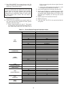
IMPORTANT: The Carrier factory default values for the
VFD may be different than the default values of the manu-
facturer. Refer to the Carrier literature when checking
default values. The following default values have been
changed from the manufacturer settings to closely match
the VFD operation with a Carrier VAV unit. Refer to
Tables 14 and 15.