


52
7. Route the wires from the enthalpy sensor to the return air
enthalpy control through the holes on the inside of the
hinged filter access panel. The holes are blocked by plug
buttons which should be removed.
8. Use field-supplied wire ties to attach the violet wire to the
+ terminal and the blue wire to the SR terminal.
9. Replace economizer filters.
10. Return power to unit.
Disable Economizer
— For applications where the economiz-
er will not be used (areas of high humidity), the economizer
should be disabled. To disable the economizer, perform the
following:
1. Turn of power. Ensure disconnect is locked out.
2. Locate the OAT (Outdoor Air Thermostat) in the right
hand outdoor air damper area.
3. Locate the splice connecting the violet wire coming from
T24 on the base control board to the red wire coming
from T29 on the base control board. Remove the wire nut
and break the red to violet wire splice.
4. Cap off both wires. When the connection is broken the
base control board is fooled into thinking that the
enthalpy is not acceptable and economizer operation is
disabled.
5. Return power to unit.
NOTE: When the economizer is disabled, the damper
will function as a 2-position damper.
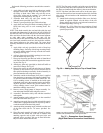
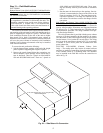
Step 11 — Position Power Exhaust/Barometric
Relief Damper Hood —
All electrical connections have
been made and adjusted at the factory. The power exhaust
blowers and barometric relief dampers are shipped assembled
and tilted back into the unit for shipping. Brackets and extra
screws are shipped in shrink wrap around the dampers. If
ordered, each unit will have 4 (48AJ,AK,AW,AY020-050 and
48EJ,EK,EW,EY024-048 units) or 6 (48AJ,AK,AW,AY060
and 48EJ,EK,EW,EY054-068 units) power exhaust blowers
and motors or 4 (48AJ,AK,AW,AY020-050 and 48EJ,EK,EW,
EY024-048 units) or 6 (48AJ,AK,AW,AY060 and 48EJ,EK,
EW,EY054-068 units) barometric relief dampers.
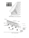
1. Remove 9 screws holding each damper assembly in
place. See Fig. 50. Each damper assembly is secured with
3 screws on each side and 3 screws along the bottom.
Save screws.
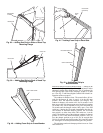
2. Pivot each damper assembly outward until edges of
damper assembly rest against inside wall of unit.
3. Secure each damper assembly to unit with 6 screws
across top (3 screws provided) and bottom (3 screws
from Step 1) of damper.
4. With screws saved from Step 1, install brackets on each
side of damper assembly.
5. Remove tape from damper blades.
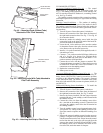
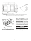
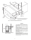
VAV DUCT PRESSURE TRANSDUCER — The VAV duct
pressure transducer (VAV inverter pressure transducer) is locat-
ed behind the filter access door on the lower inner panel. See
Fig. 51. A section of field-supplied
1
/
4
-in. plastic tubing must
be run from the high pressure tap on the differential pressure
switch and connected to a field-supplied tap in the supply-air
duct. The tap is usually located
2
/
3
of the way out on the main
supply duct. Remove plug button in panel to route tubing.
VAV BUILDING PRESSURE TRANSDUCER — The VAV
building pressure transducer (modulating power exhaust pres-
sure transducer) is located behind the filter access door on the
lower inner panel. See Fig. 51. A section of field-supplied
1
/
4
-in. plastic tubing must be run from the high pressure tap on
the differential pressure switch to the conditioned space. The
pressure tube must be terminated in the conditioned space
where a constant pressure is required. This location is usually
in an entrance lobby so that the building exterior doors will
open and close properly. Remove plug button in panel to route
tubing.
The low pressure tap is factory-routed to the atmosphere.
For a positive-pressure building, route the high tap to building
air and low tap to atmosphere. For a negative-pressure build-
ing, route the high tap to atmosphere and the low tap to build-
ing air.
Be careful when tilting blower assembly. Hoods and blow-
ers are heavy and can cause injury if dropped.
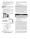
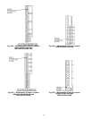
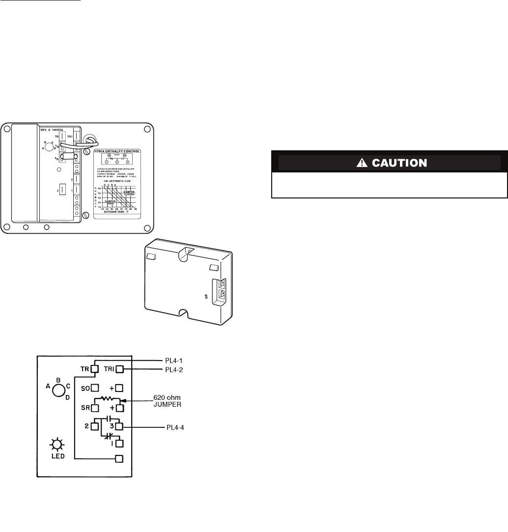
+
C7400A1004
HH57AC077
ENTHALPY
CONTROL
HH57AC078
ENTHALPY SENSOR
(USED WITH ENTHALPY
CONTROL FOR DIFFERENTIAL
ENTHALPY OPERATION)
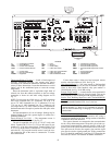
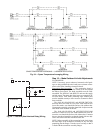
Fig. 46 — Differential Enthalpy Control and Sensor
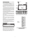
NOTE: Switches shown in high enthalpy state. Terminals 2 and 3
close on enthalpy decrease.
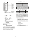
Fig. 47 — Wiring Connections for Solid-State
Enthalpy Control (HH57AC077)