


87
SUPPLY AIR TEMPERATURE RESET — Supply air tem-
perature reset is used to reset the supply-air temperature utility.
A 4 to 20 mA signal (field-supplied) is required. The reset op-
tion does not require enabling.
POWER EXHAUST OPERATION — Power exhaust has
two options (constant volume and modulating) that have the
following sequence of operation:
The constant volume power exhaust stage 1 (CVPE1) is en-
abled when the indoor fan has been energized and the desired
outdoor-air damper position for the economizer increases
above the first constant volume (CV) power exhaust stage
1 point (PES1). The PES1 factory default value is set at 25%.
The constant volume power exhaust stage 2 (CVPE2) is en-
abled when the desired outdoor-air damper position for the
economizer increases above the second CV power exhaust
stage 2 point (PES2). The PES2 factory default value is set at
75%. Each stage is disabled when the desired damper position
decreases below the respective set points.
The modulating power exhaust is enabled when the indoor
fan is energized and the building pressure has exceeded the in-
dividual sequencer set points. The default set points are 0.04 in.
wg (6.3 vdc) for stage 1, 0.10 in wg (6.8 vdc) for stage 2,
0.16 in wg (7.3 vdc) for stage 3, and 0.23 in. wg (7.8 vdc) for
stage 4, 0.29 in. wg (8.3 vdc) for stage 5, and 0.35 in. wg
(8.8 vdc) for stage 6 power exhaust sequencer. Each stage also
requires that the building pressure is reduced until it drops be-
low the disable set point. The default set points are 0 in wg.
(6.0 vdc) for stage 1, 0.060 in. wg (6.5 vdc) for stage 2, 0.13 in.
wg (7.0 vdc) for stage 3, 0.19 in. wg (7.4 vdc) for stage 4,
0.25 in. wg (8.0 vdc) for stage 5, and 0.31 in. wg (8.5 vdc) for
stage 6 power exhaust sequencer. Both of these set points are
changed at the specific controlling sequencer. It is not forcible
from CCN.
If the indoor fan is on, then PEXE = ON. If the indoor fan is
off, then PEXE = OFF. In addition, on units equipped with the
Expansion I/O module, the control module board may have di-
rect access 4 to 6 Modulated Power Exhausted stages bypass-
ing an external sequencer device. These stages will be con-
trolled directly in fire/smoke modes.
SMOKE CONTROL MODES — The 48AJ,AK,AW,AY and
48EJ,EK,EW,EY units with an optional expansion board per-
form fire and smoke control modes. The expansion board pro-
vides 4 modes which can be used to control smoke within the
conditioned area. The modes of operation are fire shutdown,
pressurization, evacuation, and smoke purge. See Table 41.
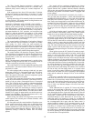
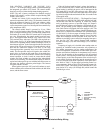
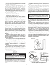
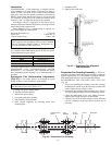
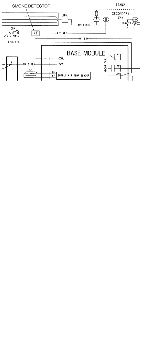
SMOKE DETECTOR — A smoke detector can be used to
initiate fire shutdown. This can be accomplished by a set of
normally closed pilot relay contacts which will interrupt power
from the 24-v transformer, secondary ‘‘B’’ terminal to the con-
trol circuit breaker (CB4). See Fig. 62. The wire that connects
these two points is white and labeled ‘‘W78.’’
NOTE: On standard gas models, the indoor fan will continue
to run 45 seconds after the call for heat has been terminated. If
fire shutdown is initiated the fan will stop immediately. No
45-second delay will occur.
The smoke detector may be mounted in the return air duct or
the supply duct. Carrier does not make recommendations as to
specific smoke detector location due to liability considerations.
INDOOR AIR QUALITY (IAQ) CONTROL — The acces-
sory IAQ sensor is required for IAQ control on the base control
board. The Carrier sensors operate with a 4 to 20 mA signal.
The 4 to 20 mA signal is connect to T13 (+) and T14 (-) on the
base control board for the IAQ sensor, and T15 (+) and T16 (-)
on the base control board for the OAQ (Outdoor Air Quality)
sensor. The sensor is field-mounted and wired to the base con-
trol board installed in the unit main control box. The IAQ sen-
sor must be powered by a field-supplied 24-V power supply
(ungrounded). Do not use the unit 24-V power supply to power
sensor.
NOTE: The Carrier IAQ/OAQ sensors are shipped configured
for a 0 to 10 Vdc signal for use on previously designed PIC
(Product Integrated Control) products. This signal must be
changed to the 4 to 20 mA signal to be used on these products,
which is accomplished through a jumper change. The IAQ/
OAQ input signals are also polarized, with (+) connecting to
the odd numbered terminals and (-) connected to the even
numbered terminals. Refer to Indoor-Air Quality Section in the
Controls, Operation, and Troubleshooting Manual for further
sequence of operation.
NOTE: The IAQ Control function was incorporated onto the
base control board on these units with serial number of 0600F
and later.
Once installed, the sensor must be enabled. The sensor is
configured with default values which may be changed through
network access software. To work properly, the IAQ sensor
high and low reference points for the sensor that is used must
match the configured values. The base control board reacts to a
4 to 20 mA signal from the IAQ sensor. The low reference
(4 mA output) must be configured to the minimum IAQ sensor
reading. The high reference (20 mA output) must be config-
ured to the maximum IAQ sensor reading.
The IAQ sensor can be configured to either low or high
priority. The priority value can be changed by the user. The
default is low.
Low priority
— When the priority is set to low, the initial con-
trol is to the IAQ set point, but the outside air damper position
will change to its minimum position when the following condi-
tions occur:
• CV units with sensor — when the space temperature is
greater than the occupied cooling set point plus 2° F or
when the space temperature is less than the occupied
heating set point minus 2° F.
• VAV units and CV units with thermostat — when the
supply-air temperature is less than the supply-air temper-
ature set point minus 8° F or when the supply-air temper-
ature is greater than the supply air temperature set point
plus 5° F for 4 minutes.
• When the outdoor air quality is greater than the outdoor
air quality set point (ppm)
High priority
— When the priority is set to high, the IAQ set
point controls the outside air damper exclusively, with no re-
gard to comfort conditioning.
TIME GUARD® CIRCUIT — The Time Guard function
(built into the rooftop control module board) maintains a mini-
mum off time of 5 minutes, a minimum on time of 10 seconds,
and a 10-second delay between compressor starts.
CRANKCASE HEATER — Unit main power supply must
remain on to provide crankcase heater operation. The crank-
case heater in each compressor keeps oil free of refrigerant
while compressor is off.
Fig. 62 — Field-Supplied Smoke Detector Wiring