


85
MORNING WARM-UP (VAV only with PC Accessed/CCN
Operation) — Morning warm-up occurs when the control has
been programmed to turn on heat prior to the Occupied mode
to be ready for occupancy mode. Morning warm-up is a condi-
tion in VAV systems that occurs when the Temperature Com-
pensated Start algorithm calculates a biased occupied start time
and the unit has a demand for heating. The warm-up will con-
tinue into the occupied period as long as there is a need for
heat. During warm-up, the unit can continue heating into the
occupied period, even if occupied heating is disabled. When
the heating demand is satisfied, the warm-up condition will ter-
minate. To increase or decrease the heating demand, use
Service Tool software to change the Occupied Heating set
point.
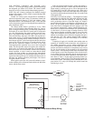
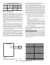
NOTE: To utilize Morning Warm-Up mode, the unit occu-
pancy schedule must be accessed via Service Tool, Building
Supervisor, or ComfortWORKS® software or accessory
Remote Enhanced Display. The PC can access the base control
board via the 3-wire communication bus or via an RJ-11 con-
nection to the CCN terminal on the base control board. See
Fig. 27.
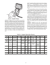
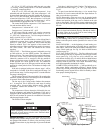
For current software (version 3.0 or later), the Low Tem-
perature Minimum Damper Position Override (LOWMDP)
has a 0 to 100% limit, with a default of 100%. Think of the
LOWMDP as a second minimum damper position. This
LOWMDP limit change requires access to the unit software
with a computer equipped with Building Supervisor, Ser-
vice Tool, or ComfortWORKS Software.
When the LOWMDP is in effect the outdoor dampers will
remain at the LOWMDP position (typically set to 0% closed)
during heating, even in the Occupied period. For the LOW-
MDP to be in effect the LOWMDP must be less than the mini-
mum damper position (MDP) and the RAT (return-air tempera-
ture) must be less than the OHSP (occupied heat set point)
minus 2.5° F. Table 40 summarizes the operational require-
ments and controlling factors for occupied heat and morning
warm-up.
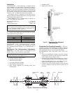
MORNING WARM-UP (VAV Only with Stand-Alone
Operation) — When the unit operates in stand-alone mode,
morning warm-up occurs when the unit is energized in Occu-
pied mode and return-air temperature (RAT) is below 68 F.
Warm-up will not terminate until the RAT reaches 68 F. The
heat interlock relay output is energized during morning warm-
up. (A field-installed 24-vdc heat interlock relay is required.)
The output will be energized until the morning warm-up cycle
is complete. Refer to Fig. 59 for heat interlock relay wiring.
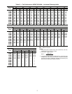
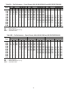
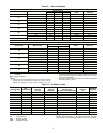
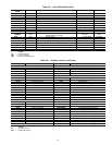
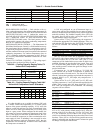
Table 39 — Navigator Display Menu Structure
RUN
STATUS
SERVICE
TEST
TEMPERATURES PRESSURES
SET
POINTS
INPUTS OUTPUTS CONFIGURATION TIME CLOCK
OPERATING
MODES
ALARMS
Auto Display
(VIEW)
SERVICE
TEST
SUPPLY AIR
TEMPERATURE
N/A
SETPOINT
SELECT
COOL
INPUT#1
HEAT
OUTPUT
1
Display
Configuration
(DISP)
Time
(TIME)
N/A
Currently
Active
Alarms
(CRNT)
Software
Version
(VERS)
HEAT
OUTPUT#1
SUPPLY AIR
TEMPERATURE 1
N/A
COOLING
SETPOINT
1
COOL
INPUT#2
HEAT
OUTPUT
2
CCN
Configuration
(CCN)
Date
(DATE)
N/A
Reset all
Current
Alarms
(RCRN)
HEAT
OUTPUT#2
SUPPLY AIR
TEMPERATURE 2
N/A
COOLING
SETPOINT
2
HEAT
INPUT#1
HEAT
OUTPUT
3
Stage Gas
Configuration
(CNFG)
Occupancy
and
Unoccupancy
Schedule
Number
(SCHD)
Alarm
History
(HIST)
HEAT
OUTPUT#3
SUPPLY AIR
TEMPERATURE 3
HEATING
SETPOINT
1
HEAT
INPUT#1
HEAT
OUTPUT
4
Reset
Alarm
History
(RHIS)
HEAT
OUTPUT#4
HEATING
SETPOINT
2
SUPPLY
FAN
STATUS
HEAT
OUTPUT
5
HEAT
OUTPUT#5
HEAT
OUTPUT
6
HEAT
OUTPUT#6
R
un Status
S
ervice
T
est
T
em
perature
s
Pre
ssures
Setpoints
Inputs
O
u
tputs
Co
nfigu
ration
T
im
e C
lock
O
pera
ting M
od
es
A
la
rm
s
ENTER
ESC
M
ODE
Alarm Status
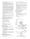
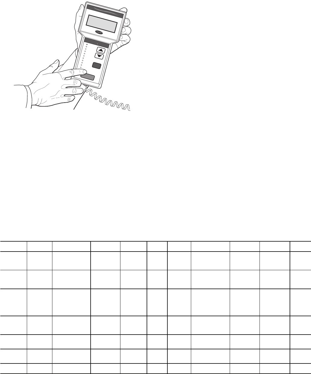
NAVIGATOR™
Comfort
Link
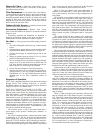
Fig. 60 — Navigator Display