


63
Power Exhaust — The optional non-modulating power
exhaust (CV only) is a two-stage design where the operation of
the exhaust fans is linked to economizer position. When the
supply fan is running and the economizer is 25% open, the base
control board closes contacts, activating 2 (48AJ,AK,AW,
AY020-050 and 48EJ,EK,EW,EY024-048) or 3 (48AJ,AK,
AW,AY060 and 48EJ,EK,EW,EY054-068) exhaust fans.
When the economizer position reaches 75% open, the base
module activates the other 2 (48AJ,AK,AW,AY020-050 and
48EJ,EK,EW,EY024-048) or 3 (48AJ,AK,AW,AY060 and
48EJ,EK,EW,EY054-068) exhaust fans. The fans will turn off
when the economizer closes below the same points. The econ-
omizer position set points that trigger the exhaust fans can be
modified, but only through use of the Service Tool, Comfort-
WORKS®, or Building Supervisor software. If single-stage
operation is desired, adjust the economizer set points to identi-
cal values at the desired point to activate all exhaust fans.
The optional modulating power exhaust (VAV standard, CV
optional) is controlled by a modular electronic sequencer sys-
tem. This system consists of a model R353 signal input module
and 4 model S353 staging modules (for 48AJ,AK,AW,AY060
and 48EJ,EK,EW,EY054-068, 6 model S353 staging mod-
ules). The signal input module receives a 0 to 10 vdc signal
from the building pressure transducer, which is mounted adja-
cent to the supply static transducer behind the filter access pan-
el. The modules are mounted just below the unit control board.
The left module is the R353, and the 4 or 6 modules on the
right are S353 modules for stages 1 through 4 or 6. On the unit
wiring label, the R353 is designated PESC, and the S353
modules are designated PES1 through PES4 (PES6 for
48AJ,AK,AW,AY060 and 48EJ,EK,EW,EY054-068).
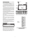
The building pressure transducer range is -0.5 to + 0.5 in.
wg. It is powered by a 0 to 10 vdc signal. A factory-installed
hose at the ‘‘Lo’’ connection leads to atmosphere, and a field-
supplied hose must be connected to the ‘‘Hi’’ connection and
led into the building to a point where building pressure is to be
controlled. There is a plug button in the bulkhead just above the
transducers, for use in leading the hoses into the building via
the return air ductwork.
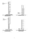
There are 3 adjustments at the R353 module, all of which
have been factory set. In the center of the circuit board is a set
of 4 pins with a jumper, labeled J2. This determines the mode
of operation. The bottom two pins must be jumpered for direct
operation. Direct operation means that the staging modules are
activated in sequence as the input signal increases.
At the upper right corner of the board is a set of 5 pins and
jumper, which determines the time constant for the control.
The time constant is the delay in response built into the con-
trols. The jumper should be on the middle or bottom two pins,
for the maximum time constant. The delay can be decreased, if
desired, by moving the jumper progressively upward, always
jumpering adjacent pins.
At the lower left corner of the board below the terminal strip
is a resistor marked R27. This must be removed in order to ob-
tain the 0 to 10 vdc signal output. There will not be a resistor on
a factory-supplied module, but a resistor may be present on a
replacement module and must be removed.
The R353 module has a terminal block with 7 connections
available for wiring. The 2 right-hand terminals are for the
24 vac and common connections. The next 2 terminals are for
the 0 to 10 vdc signal. Consult the wiring label for wire identi-
fication if replacing the module. The 3 left-hand terminals are
not used for this application.
The S353 module has an LED (light-emitting diode), a set
of 4 jumper pins, and 2 potentiometers. The LED will light
whenever the module is activated, providing a visual indication
of the number of exhaust fans running. The jumper pins are ar-
ranged in a square format. Two jumpers are used to determine
the mode of operation (direct or reverse). The 2 jumpers must
be arranged horizontally for direct action (factory set).
At the top of the module are two potentiometers. The left
potentiometer adjusts the offset. The right potentiometer ad-
justs the differential. The potentiometers are factory set for a
nominal 0 in. wg building pressure.
The offset set point is defined as the point at which a mod-
ule turns off a fan, and is measured in terms of percent of the
input signal. For control purposes, 0 offset is at an arbitrary
‘‘floor’’ which is established at 10% of the input signal, or
1 vdc. In this example, the first stage will turn off at 30%
(3 vdc), and the offset potentiometer will be set at 20%. The
second stage will turn off at 50% signal (5 vdc), and the offset
potentiometer will be set at 40%. The fourth stage is at the
maximum 75% offset, which equates to 85% signal or 8.5 vdc.
The offset potentiometer is calibrated in 10% increments.
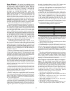
See below for building pressure to signal level.
If the building pressure is controlled at 0 in. wg, offset of the
first stage should be set at 50%, which equates to 60% of the
input signal, or 6 vdc. The other stages can then be set as de-
sired between 50% and 75%.
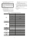
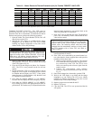
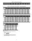
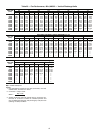
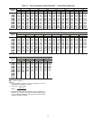
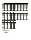
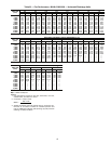
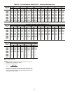
The default offset set points for modulating power exhaust
are shown in Tables 16A and 16B.
The differential set point is the difference between the turn
off point and the turn on point for each module. It also is cali-
brated in terms of percent of input signal, and has a range of
1% to 7%. The differential potentiometer is calibrated in 1%
increments, and is factory set at approximately 3%. It is recom-
mended to leave the set point at 3%, to minimize cycling of the
fans.
The offset and differential potentiometers have been factory
set for atmospheric pressure. Do not change these settings until
there is some experience with the building. In most cases the
factory settings will be satisfactory. However, if the building
pressure is not being maintained as desired, then some minor
adjusting on a trial and error basis can be made.
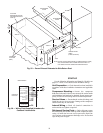
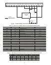
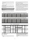
Direct Digital Controls DIP Switch Configura-
tion —
The Direct Digital Control (DDC) board must be
configured for each application. The DDC board is configured
through the DIP (Dual In-Line Package) switches located on
the board. There are 8 DIP switches which configure 8 differ-
ent applications of the DDC. See Table 17. DIP switch 1 is on
the left of the block. DIP switch 8 is on the right of the block.
To open a DIP switch, push the switch up with suitable tool
(small-blade screwdriver). To close a DIP switch, push the
switch down. Factory settings are shown in Table 18.
The DIP switch configurations are as follows:
• DIP switch 1 configures the unit to operate as a VAV or
CV unit
• DIP switch 2 configures the unit to use a space sensor
(VAV units) or a thermostat (CV units)
• DIP switch 3 configures the DDC for use with an elec-
tronic expansion board
• DIP switch 4 is used to field test the unit
• DIP switch 5 is used to enable occupied heating (VAV
units) or specify the type of power exhaust (CV units)
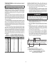
BUILDING PRESSURE SIGNAL LEVEL
(in. wg) (vdc)
-0.50 2
-0.25 4
0.00 6
0.25 8
0.50 10