


88
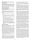
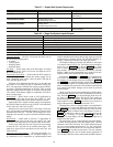
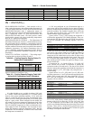
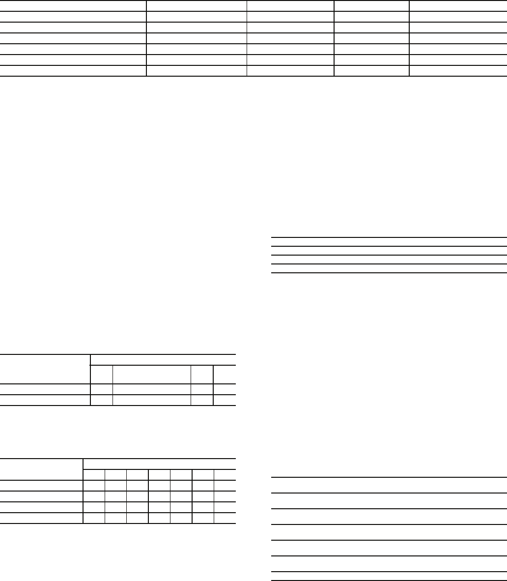
Table 41 — Smoke Control Modes
LEGEND
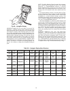
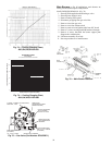
HEAD PRESSURE CONTROL — Each unit has a fan cy-
cling, outdoor thermostat to shut off the outdoor-fan motor(s) at
55 F (one outdoor-fan motor on 48AJ,AK,AW,AY020-030 and
48EJ,EK,EW,EY024-034 units, 2 outdoor-fan motors on
48AJ,AK,AW,AY035-050 and 48EJ,EK,EW,EY038-048 units
and 3 outdoor-fan motors on 48AJ,AK,AW,AY060 and
48EJ,EK,EW,EY054-068 units). The head pressure control
permits unit to operate with correct condensing temperatures
down to 35 F outdoor-air temperature.
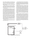
MOTORMASTER® III CONTROL — The Motormaster III
Solid-State Head Pressure Control is a field-installed accessory
fan speed control device actuated by a temperature sensor. It
is specifically designed for use on Carrier equipment and con-
trols the condenser-fan motor speed in response to the saturated
condensing temperature. For outdoor temperatures down to
–20 F, it maintains condensing temperature at 100 F. Refer to
the accessory Motormaster installation instructions for more
information.
CAPACITY CONTROL, COOLING — The cooling capaci-
ty staging tables are shown in Tables 42 and 43.
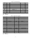
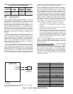
Table 42 — Cooling Capacity Staging Table, CV
Units with 2 Compressors
NOTE: On CV units that require additional unloading, add suction
pressure unloaders to Compressor 1 only.
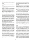
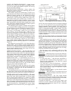
Table 43 — Cooling Capacity Staging Table VAV
Units with 2 Compressors and 2 Unloaders*
*40 ton units have only one unloader.
It is often desirable to use a variable air volume (VAV) unit
in a variable volume and temperature (VVT) control system
because of the greater unloading capability. A VAV unit (with
software version 4.0 and later) can easily be configured in the
field to run off of either space thermostat (VVT® relay pack)
input or a space sensor. When configured in this manner, the
unit control will turn on compressors based upon load in the
space. If the supply-air falls below predefined limits, the con-
trol will unload the compressor in order to maintain the mini-
mum supply-air limit. If unloading is not successful in main-
taining the minimum supply-air temperature (SAT), then the
compressors will be turned off. An alarm will be issued when
the compressors are turned off.
A VAV unit configured to run off thermostat input or a
space sensor will have the capability for two stages of heating,
however, modification to the control wiring will be required to
make this available. The Variable Frequency Drive (VFD) for
the supply fan will still be active, varying the supply air fan
speed to maintain supply duct pressure.
Upon a call for Y1 (or Y2_SPT) cooling, the compressor 1
will start after appropriate Time Guard® functions. Thirty sec-
onds after the SAT drops below the “SAT1TRIP” the compres-
sor will be unloaded. The unloading sequence will be as
follows:
The “Y1 Low SAT Limit” has an adjustable range from
50 F to 65 F, with a factory setting of 53 F. If the temperature of
the SAT rise above the “Y1 Low SAT Limit” plus 2° F, the
compressor will be loaded in the reverse order in which it was
unloaded following the pre-described time guards. There will
be a 90-second time guard between any change in unloaded
state, and the normal 5-minute time guard for change in com-
pressor On/Off state.
If compressor no. 1 is forced off due to “Y1 LOW SAT
Limit” an alert will be issued. If economizer is suitable, the
economizer mode will remain active. The alert will be cleared
after the 5-minute time guard has expired and the compressor is
restarted. With Y1 (or Y1_SPT) input, only compressor no. 1
can be running.
Upon a call for Y1 (or Y1_SPT) and Y2 (or Y2_SPT) cool-
ing both compressor no. 1 and 2 will start after appropriate time
guards. Thirty seconds after SAT drops below the “Y2 Low
SAT Limit” the compressor will be unloaded. The unloading
sequence will be as follows:
The “Y2 Low SAT Limit” has an adjustable range from
45 F to 55 F, with a factory default setting of 48 F. If the tem-
perature of the SAT rise above the “Y2 Low SAT Limit” plus
2° F, the compressor will be loaded in the reverse order in
which it was unloaded following the pre-described Time Guard
functions. There will be a 90-second time guard between any
change in unloaded state, and the normal 5-minute time guard
for change in compressor On/Off state.
DEVICE PRESSURIZATION SMOKE PURGE EVACUATION FIRE SHUTDOWN
Economizer 100% 100% 100% 0%
Indoor Fan/VFD ON ON OFF OFF
Power Exhaust (all outputs) OFF ON ON OFF
Heat Stages OFF OFF OFF OFF
Cool Stages OFF OFF OFF OFF
HIR ON ON OFF OFF
HIR — Heat Interlock Relay
VFD — Variable Frequency Drive
Stages
0
1
Economizer
23
Compressor 1 off off on on
Compressor 2 off off off on
STAGES
0123456
Compressor 1 offonononononon
Unloader 1 off on on off on on off
Unloader 2 offonoffoffonoffoff
Compressor 2 off off off off on on on
Compressor no. 1 On, Full Load Unloader no. 1 and no. 2 Off
Compressor no. 1 On,
2
/
3
Load Unloader no. 1 Off, Unloader no. 2 On
Compressor no. 1 On,
1
/
3
Load Unloader no. 1 and no. 2 On
Compressor no. 1 Off Unloader no. 1 and no. 2 Off
Compressor no. 1
On, Full Load
Unloader no. 1 and no. 2 Off Compressor no. 2 On
Compressor no. 1
On,
2
/
3
Load
Unloader no. 1 Off,
Unloader no. 2 On
Compressor no. 2 On
Compressor no. 1
On,
1
/
3
Load
Unloader no. 1 and no. 2 On Compressor no. 2 On
Compressor no. 1
On, Full Load
Unloader no. 1 and no. 2 Off Compressor no. 2 Off
Compressor no. 1
On,
2
/
3
Load
Unloader no. 1 Off,
Unloader no. 2 On
Compressor no. 2 Off
Compressor no. 1
On,
1
/
3
Load
Unloader no. 1 and no. 2 On Compressor no. 2 Off
Compressor no. 1 Off Unloader no. 1 and no. 2 Off Compressor no. 2 Off