


43
Routing Through Bottom of Unit
— If wiring is brought in
through bottom of unit, use field-supplied watertight conduit to
run power wiring from basepan out through bottom 3
1
/
2
-in.
hole to the disconnect box and back into unit to the main con-
trol box.
Use strain relief going into control box through 2
1
/
2
-in. di-
ameter hole provided. After wires are in unit control box, con-
nect to power terminal block (see Power Wiring section on
page 33).
Low-voltage wiring must be run in watertight conduit from
the basepan to control box and through
7
/
8
-in. diameter hole
provided in bottom of unit control box. Field-supplied strain re-
lief must be used going into the box. After wiring is in control
box, make connections to proper terminals on terminal blocks
(see Field Control Wiring section on this page).
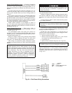
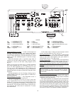
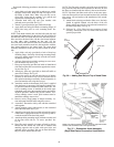
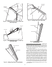
Install conduit connector in unit basepan as shown in
Fig. 5-16. Route power and ground lines through connector to
terminal connections in unit control box as shown on unit wir-
ing diagram and Fig. 28.
Routing Through Side of Unit
— Route power wiring in
field-supplied watertight conduit into unit through 2
1
/
2
-in. or
3-in. hole. See Fig. 28.
Use field-supplied strain relief going into control box
through 2
1
/
2
-in. or 3-in. diameter hole provided. After wires are
in unit control box, connect to power terminal block (see Pow-
er Wiring section on page 33).
Bring low-voltage control wiring through factory-drilled
7
/
8
-in. diameter hole in condenser side post. Use strain relief
going into
7
/
8
-in. diameter hole in bottom of unit control box.
After wiring is in control box, make connection to proper
terminals on terminal blocks (see Field Control Wiring section
below).
Affix crankcase heater sticker (located in the installers pack-
et) to unit disconnect switch.
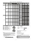
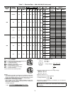
Voltage to compressor terminals during compressor opera-
tion must be within the voltage range indicated on the unit
nameplate. On 3-phase units, phases must be balanced within
2%.
Use the formula in Tables 7 and 8 to determine the percent-
age of voltage imbalance.
Unit failure as a result of operation on improper line voltage
or excessive phase imbalance constitutes abuse and may cause
damage to electrical components.
On 208/230-v units, transformer no. 1 is wired for 230-v. If
208/230-v unit is to be run with 208-v power supply, the trans-
former must be rewired as follows:
1. Remove cap from red (208 v) wire.
2. Remove cap from spliced orange (230 v) wire. Discon-
nect orange wire from black unit power wire.
3. Cap orange wire.
4. Splice red wire and black unit power wire. Cap wires.
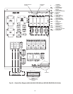
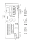
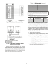
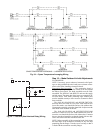
FIELD CONTROL WIRING — Install either a Carrier-
approved thermostat or a CCN (Carrier Comfort Network)
compatible temperature sensor. Thermostats are used on CV
(constant volume) units only. Control box diagrams are shown
in Fig. 29-31.
IMPORTANT: The VAV (variable air volume) units use
variable frequency drives, which generate, use and can
radiate radio frequency energy. If units are not installed and
used in accordance with these instructions, they may cause
radio interference. They have been tested and found to
comply with limits of a Class A computing device as
defined by FCC (Federal Communications Commission)
regulations, Subpart J of Part 15, which are designed to
provide reasonable protection against such interference
when operated in a commercial environment.
The unit must be electrically grounded in accordance with
local codes and NEC ANSI/NFPA 70 (National Fire Pro-
tection Association).
IMPORTANT: If the supply voltage phase imbalance is
more than 2%, contact your local electric utility company
immediately.
IMPORTANT: BE CERTAIN UNUSED WIRES ARE
CAPPED. Failure to do so may damage the transformers.
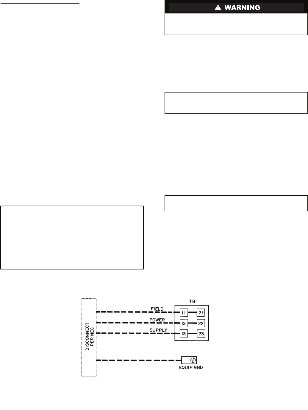
Fig. 28 — Field Power Wiring Connections
LEGEND
GND — Ground
NEC — National Electrical Code
TB — Terminal Block