


94
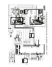
Main Burners — For all applications, main burners are
factory set and should require no adjustment.
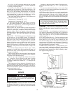
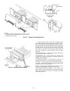
MAIN BURNER REMOVAL (Fig. 76)
1. Shut off (field-supplied) manual main gas valve.
2. Shut off power supply to unit.
3. Remove heating access panel.
4. Disconnect gas piping from gas valve inlet.
5. Remove wires from gas valve.
6. Remove wires from rollout switch.
7. Remove sensor wire and ignitor cable from IGC board.
8. Remove 2 screws securing manifold bracket to basepan.
9. Remove 4 screws that hold the burner support plate
flange to the vestibule plate.
10. Lift burner assembly out of unit.
11. Reverse procedure to re-install burners.
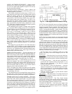
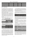
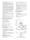
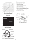
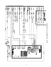
Liquid Pressure at Liquid Valve (PSIG)
CHARGING CHART
BOTH CIRCUITS
ALL OUTDOOR FANS MUST BE OPERATING
Liquid Temperature at Liquid Valve (deg F)
140
120
100
80
60
40
50 100 150 200 250 300 350 400
Add Charge if Above Curve
Reduce Charge if Below Curve
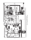
Fig. 73 — Cooling Charging Chart,
48EJ,EK,EW,EY054-068
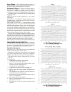
Fig. 74 — Cooling Charging Chart,
48AJ,AK,AW,AY020-060
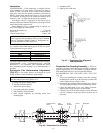
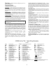
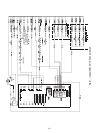
OFF
ON
W-1
W-2
D-1
D-2
C1
C2
PILOT
ADJ.
INLET PRESSURE TAP
(PLUGGED)
1/8 - 27 N.P.T. THDS.
2 LEADS, #18 WIRE 1/32 INSULATION,
600V. MAX., 105°C
REGULATOR
ADJUSTMENT SCREW
(REMOVE COVER)
OUTLET PRESSURE
TAP (PLUGGED)
1/8-27 N.P.T. THDS.
PILOT CONNECTION
FOR 1/4” O.D. TUBING
(PLUGGED)
RECEPTACLE AND
TAB COMBINATION
TERMINAL
RECEPTACLE TERMINAL
Fig. 75 — Gas Valve (Part Number EF33CB271)
Fig. 76 — Main Burner Removal