


92
5. Be sure that hub flanges, flex members, spacer, and hard-
ware are clean and free of oil.
6. Place the flanges onto the shafts with the hub facing out-
ward. Do not tighten the set screws at this time.
7. Outside of the unit, assemble the flex members to the cen-
ter drive shaft with 4 bolts and nuts. The flex members
have collars that need to be inserted into the smaller hole
of the drive shaft flange.
8. Assemble the flex member/drive shaft assembly to one of
the shaft flanges, using 2 bolts and nuts. Slide the other
shaft flange towards the assembly and assemble using 2
bolts and nuts. If the shafts are not misaligned, the collar in
the flex member should line up with the shaft flange holes.
9. Torque nuts properly to 95 to 100 ft-lb. Do not turn a cou-
pling bolt. Always turn the nut. Always use thread lubri-
cant or anti-seize compound to prevent thread galling.
10. The ends of the shafts should be flush with the inside of
the shaft flange. Torque the set screws to 25 ft-lb.
11. After assembly is complete, slowly rotate the shafts by
hand for 30 to 60 seconds.
12. Tighten the bearing mounting bolts, using care not to
place any loads on the shaft which would cause flexure to
the shafts.
13. Reinstall drive belts. (Refer to Belt Tension Adjustment
section below.)
14. Visually inspect the assembly. If the shafts are overly mis-
aligned, the drive shaft flange will not be parallel with the
shaft flanges.
15. Recheck nut torque after 1 to 2 hours of operation. Bolts
tend to relax after being initially torqued.
Evaporator Fan Service and Replacement
1. Turn off unit power supply.
2. Remove supply-air section panels.
3. Remove belt and blower pulley.
4. Loosen setscrews in blower wheels.
5. Remove locking collars from bearings.
6. Remove shaft.
7. Remove venturi on opposite side of bearing.
8. Lift out wheel.
9. Reverse above procedure to reinstall fan.
10. Check and adjust belt tension as necessary.
11. Restore power to unit.
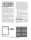
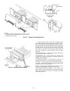
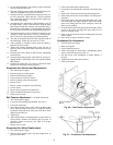
Belt Tension Adjustment — To adjust belt tension:
1. Turn off unit power supply.
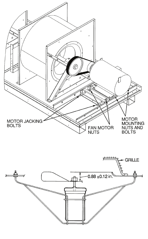
2. Loosen motor mounting nuts and bolts. See Fig. 69.
3. Loosen fan motor nuts.
4. Turn motor jacking bolts to move motor mounting plate
left or right for proper belt tension. A slight bow should
be present in the belt on the slack side of the drive while
running under full load.
5. Tighten nuts.
6. Adjust bolts and nut on mounting plate to secure motor in
fixed position. Recheck belt tension after 24 hours of
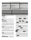
operation. Adjust as necessary. See Table 3 for proper
tension values.
7. Restore power to unit.
Evaporator-Fan Motor Replacement
1. Turn off unit power supply.
2. Remove upper outside panel and open hinged door to
gain access to motor.
3. Fully retract motor plate adjusting bolts.
4. Loosen the 2 rear (nearest the evaporator coil) motor plate
nuts.
5. Remove the 2 front motor plate nuts and carriage bolts.
6. Slide motor plate to the rear (toward the coil) and remove
fan belt(s).
7. Slide motor plate to the front and hand tighten one of the
rear motor plate nuts (tight enough to prevent the motor
plate from sliding back but loose enough to allow the
plate to pivot upward).
8. Pivot the front of the motor plate upward enough to allow
access to the motor mounting hex bolts and secure in
place by inserting a prop.
9. Remove the nuts from the motor mounting hex bolts and
remove motor.
10. Reverse above steps to install new motor.
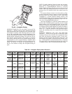
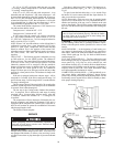
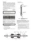
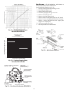
Condenser-Fan Adjustment
1. Turn off unit power supply.
2. Remove fan guard.
3. Loosen fan hub setscrews.
4. Adjust fan height on shaft using a straightedge placed
across venturi and measure per Fig. 70.
5. Fill hub recess with permagum if rubber hubcap is
missing.
6. Tighten setscrews and replace panel(s).
7. Turn on unit power.
Fig. 69 — Belt Tension Adjustment
Fig. 70 — Condenser-Fan Adjustment