


59
Crankcase Heaters —
Crankcase heaters are energized
as long as there is power to the unit, except when the compres-
sors are operating.
Variable Frequency Drive (VFD) —
The variable
frequency drives are factory set. These settings include factory-
installed jumpers and software configurations. The only field
configured set point is duct static pressure. A Toshiba Opera-
tion Manual is shipped with each VAV unit. This manual
should be used if the drive needs to be customized for a partic-
ular application.
NOTE: The VFD will always provide the proper phase
sequence to the indoor-fan motor. The indoor-fan motor oper-
ates in proper rotation regardless of the phase sequence to the
unit. If, upon start-up, the outdoor fans operate backwards but
the indoor fan operates in the correct direction, reverse any two
leads to the main terminal block. All fans will then operate in
the correct direction.
A factory-supplied 2-wire duct pressure transducer is sup-
plied and wired complete with cable ground to reduce electrical
noise. A
1
/
4
-in. air pressure tube must be routed to a location in
the supply air ductwork where it can sense supply air duct pres-
sure. The recommended location is about
2
/
3
of the way out on
the supply ductwork, so that a steady pressure will be provided
for the transducer.
To set the duct static pressure, perform the following steps.
The factory setting is zero. The duct transducer has a range
from 0 to 5 in. wg. The transducer output is 4 to 20 mA, there-
fore, 0 to 5 in. wg is proportional to the 4 to 20 mA and must be
expressed to the VFD in terms of percentage of the frequency
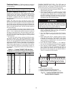
range. Refer to Table 11. The set point value is a percentage of
the maximum output frequency. Locate the duct static pressure
closest to that desired and use the corresponding set point val-
ue. If necessary, interpolation between duct static pressures is
permissible.
Table 11 — Toshiba TOSVERT VFD Set Point
(Frequency Command) for Supply Duct Pressure
TOSHIBA TOSVERT130-E3 VFD — The VFD must be
powered up, however, since it is located near the indoor fan,
operation of the fan is not desirable. To disable the fan and set
the duct static pressure, perform the following procedure:
1. Open the Indoor Fan Circuit Breaker (IFCB). This will
shut off power to the VFD.
2. Wait for the VFD display to go blank and remove VFD
cover without touching any interior components. Make
sure that the charge indicator lamp is out, indicating that
the VFD is discharged. The lamp is located on the upper
right hand corner of the terminal block. It may take sever-
al minutes for the VFD to fully discharge.
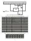
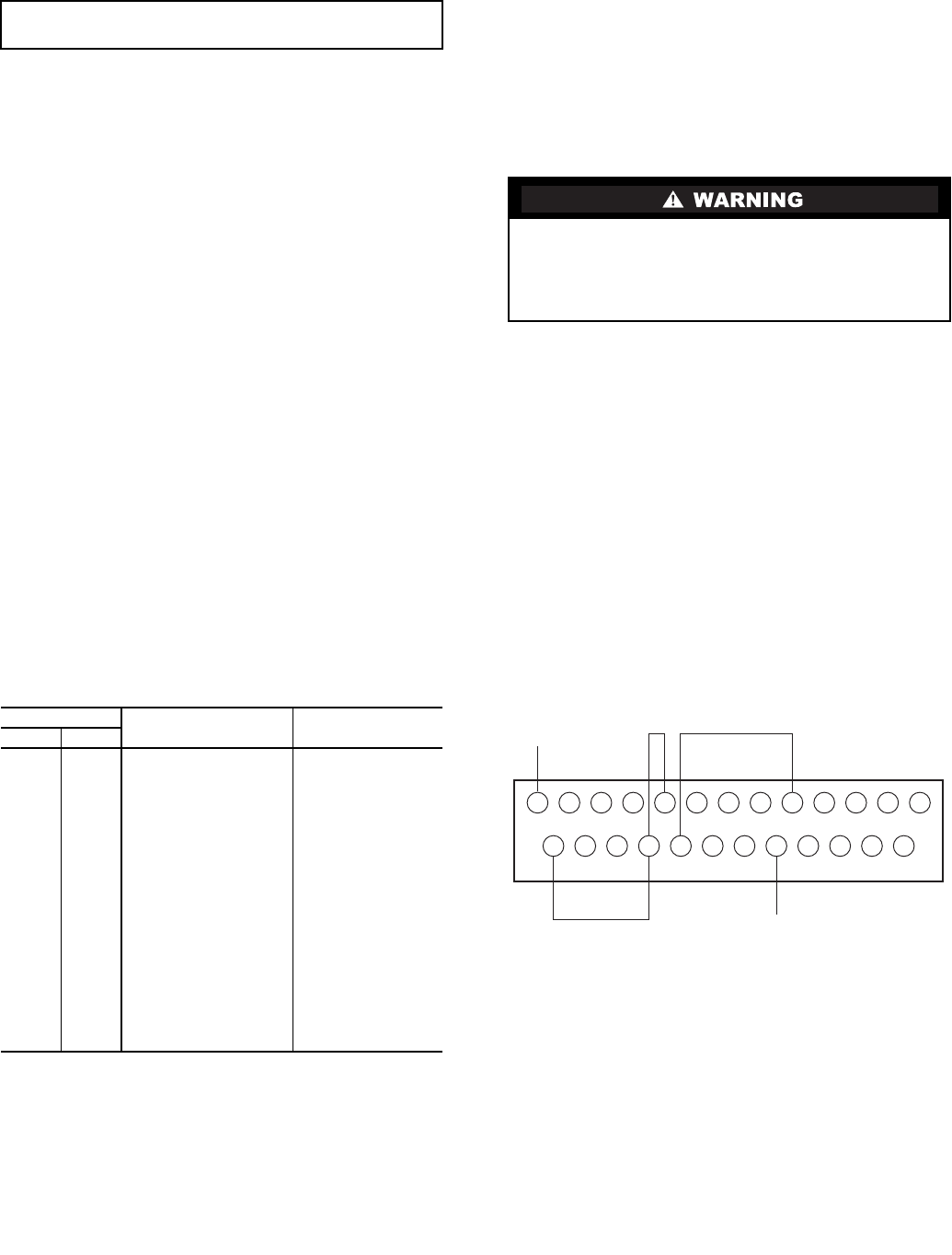
3. Remove jumper between ST and CC on the terminal
block and replace the VFD cover. This will disable the
running of the VFD. Refer to Fig. 57.
4. Close the IFCB and energize the Indoor Fan Contactor
(IFC). The VFD is now powered but the fan will not
operate.
5. On the front of the VFD is a keypad, which is used to
change the VFD set point. At this point the drive should
be disabled and the display read “OFF”. If the current
output frequency is displayed then verify that the ST and
CC jumpers have been removed.
6. Press either the “DOWN ARROW” or “UP ARROW”
key once, this will display the current frequency set point.
7. Press either the “DOWN ARROW” or “UP ARROW”
key to change set point to the appropriate duct static set
point desired. This number may be adjusted based on
the amount of static pressure (in. wg) required. Refer to
Table 11 to identify the VFD Set Point.
IMPORTANT: Unit power must be on for 24 hours prior to
start-up. Otherwise, damage to compressor may result.
PRESSURE
CONTROL SIGNAL
(mA)
VFD SET POINT
(Hz)
in. wg kPa
0.0 0.000
4.0 0
0.25 0.062
4.8 3
0.50 0.124
5.6 6
0.75 0.187
6.4 9
1.00 0.249
7.2 12
1.25 0.311
8.0 15
1.50 0.373
8.8 18
1.75 0.435
9.6 21
2.00 0.498
10.4 24
2.25 0.560
11.2 27
2.50 0.622
12.0 30
2.75 0.684
12.8 33
3.00 0.747
13.6 36
3.25 0.809
14.4 39
3.50 0.871
15.2 42
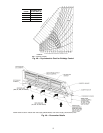
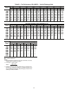
A high voltage potential can exist with the indoor fan cir-
cuit breaker open. The charge LED, located in the top
right-hand corner of the Toshiba TOSVERT130-E3 VFD
control board, will indicate charged capacitors. DO NOT
TOUCH internal high voltage parts if LED is lit.
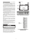
FLA
LOW
LOWP24 RCH S4 S3 S2 S1 RFRRRESP24
FLBFLCFPIVPPRXCCCCAMFM
ST
DP
DP
+
NOTES:
1. Drive enable (ST to CC made).
2. No emergency off command (S4 to CC made).
3. Direction command (F or R to CC made).
4. Frequency reference (4-20mA signal at IV terminal).
Fig. 57 — Toshiba TOSVERT130-E3 VFD
Factory-Installed Jumpers