


44
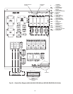
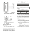
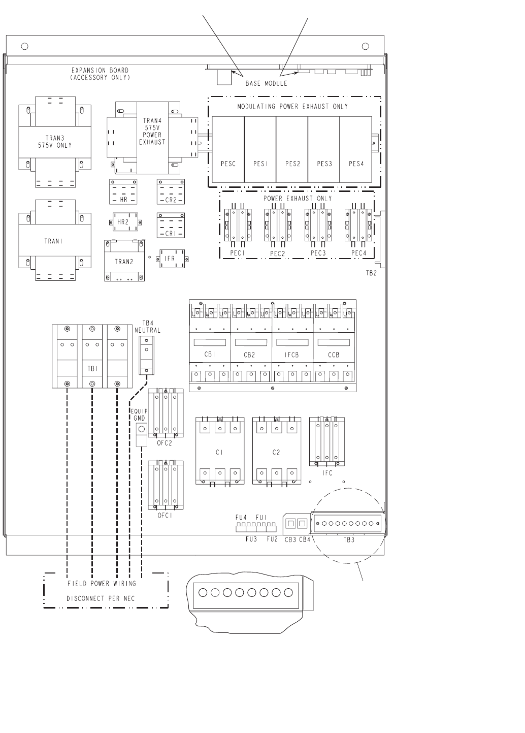
SEE DETAIL A
DIP SWITCHES
(FAR SIDE)
SENSOR CONNECTION
LOCATION
R Y1 Y2 W1 W2 G C X
DETAIL A
(THERMOSTAT CONNECTION
LOCATION)
TB3
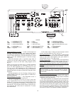
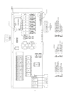
Fig. 29 — Control Box Diagram (48AJ,AK,AW,AY020-030 and 48EJ,EK,EW,EY024-034 Units)
LE
G
END
C—Compressor/
Contactor
CB — Circuit Breaker
CCB — Control Circuit
Breaker
CR — Control Relay
DIP — Dual In-Line Package
EQUIP — Equipment
FU — Fuse
GND — Ground
HR — Heater Relay
IFC — Indoor-Fan Circuit
IFCB — Indoor-Fan
Circuit Breaker
IFR — Indoor-Fan Relay
NEC — National Electrical
Code
OFC — Outdoor-Fan
Contactor
PEC — Power Exhaust
Controller
PES — Power Exhaust
Sequencer
PESC — Power Exhaust
Sequencer Controller
TB — Terminal Block
TRAN — Transformer