


58
START-UP
Use the following information and Start-Up Checklist on
pages CL-1 and CL-2 to check out unit PRIOR to start-up.
Unit Preparation — Check that unit has been installed in
accordance with these installation instructions and applicable
codes.
Compressor Mounting — Loosen the compressor
hold-down bolts until sidewise movement of the washer under
each holddown bolt head can be obtained. Do not loosen com-
pletely as bolts are self-locking and will maintain adjustment.
Service Valves — Ensure that the suction, discharge, and
liquid line service valves are open. Damage to the compressor
could result if they are left closed.
Internal Wiring — Check all electrical connections in
unit control boxes; tighten as required.
Refrigerant Service Ports — Each refrigerant system
has one suction port located in the top of the compressor motor
casing. All units also have one service port on the liquid line
valve and one on the compressor discharge valve. Be sure that
caps on the ports are tight.
42.56”
42” MIN.
S/A
R/A
ECONOMIZER
HOOD
ECONOMIZER
HOOD
J BOX
PLENUM RATED
CABLE
(FIELD SUPPLIED)
12.94
(UNIT
OPENING)
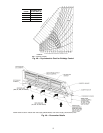
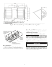
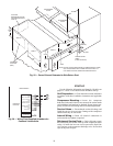
NOTE: 024-048, 020-050 SIZES SHOWN (2 POWER EXHAUST FANS)
060, 054-068 SIZES HAVE 3 POWER EXHAUST FANS. ALL
UNIT SIZES HAVE THE SAME SIZE POWER EXHAUST.
“END #2”
“END #1”
ALTERNATE
LOCATION
(END)
23.28”
TYP
42.62
TYP
LOCATION
BAROMETRIC RELIEF
OR POWER EXHAUST
“SIDE #2”
23.28”
“SIDE #1”
42.62”
J BOX
R/A
S/A
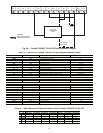
Fig. 55 — Power Exhaust Relocated to Side Return Duct
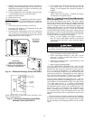
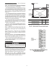
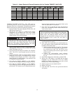
BASE MODULE
UL2
UL1
COMP #2 UNLOADER
COM
COMP #1 UNLOADER
CYCLIC COND FAN
COM
CONT COND FAN
POWER EXHAUST
COM
POWER EXHAUST
ELEC HEAT 2
COM
ELEC HEAT 1
ECONOMIZER
4-20 mA OUPUT
T26
T28
T29
T30
T33
T39
T38
T37
T36
T35
T34
T31
T32
DISCRETE
OUTPUTS
Fig. 56 — Wiring Field-Supplied Unloaders for
Constant Volume Units