


57
Step 13 — Field Modifications
DUCTWORK
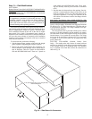
Bottom Return Units (48AJ,AK,EJ,EK) Field-Modified for
Side Return — 48AJ,AK and 48EJ,EK units with bottom re-
turn air connections may be field-modified to accommodate
side return air connections.
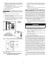
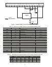
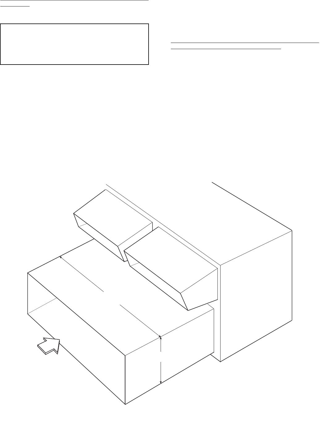
Conversion to horizontal return requires that the bottom re-
turn openings of the unit must be sealed with airtight panels ca-
pable of supporting the weight of a person. The return duct-
work connection locations on the side of the unit are higher
than normal (31-in. high). Unit-mounted power exhaust or
barometric relief cannot be used because of return air ductwork
will cover the power exhaust or barometric relief installation
locations. Power exhaust or barometric relief may be installed
in the return air ductwork.
To convert the unit, perform the following:
1. Seal the bottom return openings of the unit with airtight
panels capable of supporting the weight of a person.
2. Remove the panels located below the economizer out-
door air dampers. These openings will be used for the re-
turn air ductwork. There are 2 panels on 48AJ,AK020-
050 and 48EJ,EK024-048 units. There are 3 panels on
48AJ,AK060 and 48EJ,EK054-068 units. These open-
ings are normally used for power exhaust or barometric
relief.
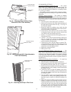
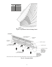
3. Run the return air ductwork up to the openings. One sin-
gle duct is recommended to connect to the unit over the
return air openings. See Fig. 54. The return duct must in-
corporate a minimum
3
/
4
-in. flange for connection to the
unit cabinet. The unit does not have duct flanges for this
conversion.
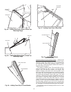
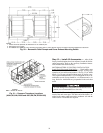
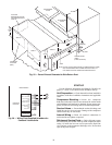
Side Supply and Return Units (48AW,AY,EW,EY) With
Field-Installed Power Exhaust in Return Duct — Space must
be available in the return duct to mount the power exhaust fan
(gravity relief) modules. Dimensions and suggested locations
are shown in Fig. 55. These instructions are a guideline and not
a comprehensive procedure. The design contractor must pro-
vide some design initiative.
The wiring harness that is provided with the power exhaust
accessory is not long enough for the fan modules to be mount-
ed in the return air duct. Field-supplied wiring must be spliced
into the harness. Use a junction box at each splice. The wiring
may be run in the return duct as shown in Fig. 55, or externally
in conduit. A service access panel will be needed near each
power exhaust fan.
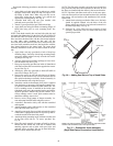
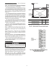
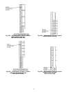
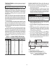
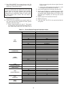
ELECTRIC UNLOADERS (Constant Volume Units
Only) — The rooftop units with version 4.0 control software
and later are capable of controlling electronic unloaders when
in the constant volume (CV) operating mode. The unloaders
may be installed in the field and wired to the control box as
shown in Fig. 56.
IMPORTANT: The following section is a guideline and not
a comprehensive procedure to field modify the units. The
installing contractor must provide some design initiative.
Field-conversion is complex and is not recommended.
Units with electric heat must not be converted because of
potential heating mode operating problems.
31.25”
INSIDE
RA
97.78” (020-050)(024-048), 150.47” (060)(054-068)
INSIDE DIMENSION
Fig. 54 — Side Return Air Conversion