


83
GAS HEATING, VARIABLE AIR VOLUME (VAV)
UNITS — All of the gas heating control is performed through
the integrated gas control (IGC) board. The control module
board serves only to initiate and terminate heating operation.
NOTE: The unit is factory-configured for disabled occupied
heating. DIP switch 5 is used to enable occupied heating (DIP
switch 5 set to OPEN).
Variable Air Volume (VAV) occupied heat is controlled by
return-air temperature (RAT) using a 5k thermistor located just
below the outdoor-air dampers. A VAV unit without a space
temperature sensor is also controlled by RAT. A VAV unit with
a space temperature sensor has Unoccupied Heat controlled by
space temperature (SPT).
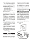
The control module board is powered by 24 vac. When
there is a call for heating (either Morning Warm-Up, Unoccu-
pied, or Occupied modes), power is sent from the control mod-
ule board to W on each of the IGC boards and W2 of the main
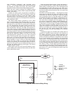
gas valve. When heating, the control module board will ener-
gize a field-supplied heat interlock relay output to drive the
VAV terminal boxes wide open. The HIR is not required on a
DAV system. See Fig. 59. In the Occupied mode the indoor-fan
motor will be operating and the outdoor-air dampers will be in
the minimum position. In the Unoccupied mode the indoor-fan
motor will be off, but will energize 45 seconds after the call for
heat and the outdoor-air dampers will move to the IAQ
Unoccupied position (generally set to zero in the Unoccupied
mode). The duct pressure sensor will signal to the variable fre-
quency drive to operate at full speed since all terminals have
been driven open. An LED on the IGC board will be on during
normal operation. A check is made to ensure that the rollout
switches and limit switches are closed and the induced-draft
motors are not running. The induced-draft motors are then en-
ergized and when speed is proven with the hall effect sensor on
the motor, the ignition activation period begins. The burners
will ignite within 5 seconds.
When ignition occurs the IGC board will continue to moni-
tor the condition of the rollout and limit switches, the hall effect
sensor, and the flame sensor.
If the call for heat lasted less than 1 minute, the heating cy-
cle will not terminate until 1 minute after heat became active.
When heating is satisfied, the power will be interrupted to the
IGC board and W1 and W2 of the main gas valve. If the unit is
controlled through a room sensor, the indoor fan will be operat-
ing in the Occupied mode and turned off after 45 seconds in the
Unoccupied mode.
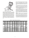
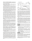
STAGED GAS UNIT HEATING — The Staged Gas Control
option offered on 48EJ,EK,EW,EY024-068 and 48AJ,AK,AW,
AY020-060 units adds the capability to control the rooftop
unit’s gas heating system to a specified Supply Air Tempera-
ture Set Point for purposes of tempering a cool mixed-air con-
dition. The gas heating system employs multiple heating sec-
tions. Each section is equipped with a two-stage gas valve. The
gas valves are sequenced by a factory-installed staged gas con-
troller (SGC) as required to maintain the user-specified Supply
Air Set Point. Up to eleven stages of heating control are avail-
able, based on quantity and heating capacity sizes of the indi-
vidual heat exchanger sections provided in the base unit. In
addition to providing system control for tempering heat opera-
tion, the new SGC also controls Demand Heat sequences
for both First-Stage (W1) and Second-Stage (W2 or full-fire)
operation.
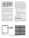
Tempering of supply air is desirable when rooftop units are
operating in ventilation mode (economizer only operation) at
low outdoor temperatures. At low outdoor temperatures, the
mixed air temperature (combination of return-from-space tem-
perature and outdoor/ventilation air temperature) may become
too low for the comfort of the occupants or for the terminal
reheat systems. The tempering function adds incremental steps
of heat capacity to raise the temperature of the mixed air up to
levels suitable for direct admission into the occupied space or
to levels consistent with reheat capabilities of the space termi-
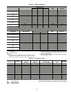
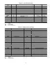
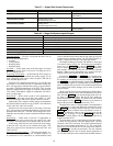
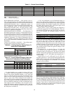
nals. Refer to Table 37 for the staged gas heating control sys-
tem components. Refer to Table 38 for the heating system con-
troller (SGC) inputs. The heating system controller (SGC) out-
puts consist of six relays (K1 through K6) which control the
individual gas valves.
BASE MODULE
CONTROL BOARD
T
30
T29
T
28
COM
COM
B
TRAN2
SECONDARY
24 VOLT
CB4
3.2 AMPS
INDOOR FAN RELAY
HIR
FIELD
INSTALLED
(HN61KK040)
(24V, 9.5VA)
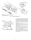
Fig. 59 — Heat Interlock Relay Wiring
LEGEND
CB — Circuit Breaker
COM — Common
HIR — Heat Interlock Relay
T—Terminal
TRAN — Transformer