


82
The Time Guard® function maintains a minimum off
time of 5 minutes, a minimum ON time of 10 seconds, and a
minimum delay before starting the second compressor of
10 seconds.
If the compressors have been off for more than 15 minutes
and the OAT (outdoor-air temperature) is less than 45 F, then
the safeties will be ignored for 5 minutes. At all times, safeties
will be used.
Heating and cooling will be mutually locked out on demand
on a first call basis. The heating and the cooling functions can-
not be operating simultaneously.
COOLING, VARIABLE AIR VOLUME (VAV) UNITS —
On power up, the control module will activate the initialization
software of the control board. The initialization software then
reads DIP switch no. 1 position to determine CV or VAV oper-
ation. Initialization clears all alarms and alerts, re-maps the in-
put/output database for VAV operation, sets maximum heat
stages to 1 and sets maximum cool stages to 6. The control
module reads DIP switch no. 3 and determines if the unit will
use expansion board operation. Power up takes a random time
of 1 to 63 seconds plus 5 minutes the first time power is sent to
the control board after a power outage.
The control module will determine if an interface (linkage)
is active and if the unit will operate in a Digital Air Volume
(DAV) mode. In a DAV system, the room terminals are
equipped with microprocessor controls that give commands to
the base unit module. If an interface is active, the control will
replace local comfort set points, space and return air tempera-
tures and occupancy status with the linkage data supplied.
The control module will determine occupancy status from
Time Schedules (if programmed), Remote Occupied/Unoccu-
pied input, global occupancy, or DAV. If Temperature Com-
pensated Start is active, the unit will be controlled as in the
Occupied mode.
NOTE: The temperature compensated start is a period of time
calculated to bring the unit on while in Unoccupied mode to
reach the occupied set point when occupancy occurs.
The control module will set the appropriate operating mode
and fan control. The control module will turn VFD on if Occu-
pied mode is evident.
For units equipped with a start/stop switch only (no space
temperature sensor), if in Unoccupied mode and valid return-
air temperature reading is available (either from a sensor or
DAV), the control will monitor return-air temperature against
Unoccupied Heat and Cool set points.
For units with a start/stop switch and a space temperature
sensor, the control module will start the VFD whenever SPT is
outside of the set points (Unoccupied Heat or Unoccupied
Cool). The VFD may also be started by nighttime thermostat
via remote Occupied/Unoccupied input or by a Temperature
Compensated Start algorithm. When VFD is running in a nor-
mal mode, the control will start heating or cooling as required
to maintain supply-air temperature at the supply air set point
(SASP) plus the reset (when enabled). The reset value is deter-
mined by SAT (supply-air temperature) reset and/or space tem-
perature reset algorithms. The space temperature reset is only
available when enabled through software.
When cooling, the control will energize the power exhaust
enable output to the external power exhaust controller, when
power exhaust is used.
If in Occupied mode, the control module will perform econ-
omizer control (economizer control same as described above
for CV units). If in Unoccupied mode, the control module will
perform nighttime free cool and IAQ pre-occupancy purge as
required (when enabled through software). When DX (direct
expansion) cooling is called, the outdoor fans will always
operate.
The control will run continuous diagnostics for alarms/
alerts; respond to CCN communications and perform any con-
figured network POC (product outboard controls) functions
such as time and outdoor-air temperature broadcast and global
broadcast; and perform Fire/Smoke control if equipped with
power exhaust.
GAS HEATING, CONSTANT VOLUME (CV) UNITS —
The gas heat units incorporate 2 (48AJ,AK,AW,AY020-050
and 48EJ,EK,EW,EY024-048) or 3 (48AJ,AK,AW,AY060 and
48EJ,EK,EW,EY054-068) separate systems to provide gas
heat. Each system incorporates its own induced-draft motor, In-
tegrated Gas Control (IGC) board, 2 stage gas valve, manifold,
etc. The systems are operated in parallel; for example, when
there is a call for first stage heat, all induced-draft motors oper-
ate, all gas valves are energized, and both IGC boards initiate
spark.
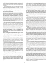
All of the gas heating control is performed through the IGC
boards (located in the heating section). The control module
board serves only to initiate and terminate heating operation.
The control module board is powered by 24 vac. When the
thermostat or room sensor calls for heating, power is sent from
the control module board to W on each of the IGC boards. An
LED on the IGC board will be on during normal operation. A
check is made to ensure that the rollout switches and limit
switches are closed and the induced-draft motors are not run-
ning. The induced-draft motors are then energized, and when
speed is proven with the hall effect sensor on the motor, the
ignition activation period begins. The burners will ignite within
5 seconds.
When ignition occurs the IGC board will continue to moni-
tor the condition of the rollout and limit switches, the hall effect
sensor, as well as the flame sensor. If the unit is controlled
through a room thermostat set for fan auto., 45 seconds after
ignition occurs, the indoor-fan motor will be energized and the
outdoor-air dampers will open to their minimum position. If for
some reason the overtemperature limit opens prior to the start
of the indoor fan blower, on the next attempt, the 45-second de-
lay will be shortened to 5 seconds less than the time from initi-
ation of heat to when the limit tripped. Gas will not be inter-
rupted to the burners and heating will continue. Once modified,
the fan on delay will not change back to 45 seconds unless
power is reset to the control. If the unit is controlled through a
room sensor, the indoor fan will be operating in the Occupied
mode and the outdoor-air dampers will be in the minimum
position.
If the unit is controlled with a room sensor in the Unoccu-
pied mode, the indoor fan will be energized through the IGC
board with a 45-second delay and the outside-air dampers will
move to the IAQ position (generally set to zero in the Unoccu-
pied mode). The IAQ feature is enabled through system soft-
ware. If IAQ is not enabled, dampers will move to the mini-
mum position.
When additional heat is required, W2 closes and initiates
power to the second stage of the main gas valves. When the
thermostat is satisfied, W1 and W2 open and the gas valves
close interrupting the flow of gas to the main burners. If the call
for W1 lasted less than 1 minute, the heating cycle will not ter-
minate until 1 minute after W1 became active. If the unit is
controlled through a room thermostat set for fan auto., the
indoor-fan motor will continue to operate for an additional
45 seconds then stop and the outdoor-air dampers will close. If
the overtemperature limit opens after the indoor motor is
stopped within 10 minutes of W1 becoming inactive, on the
next cycle the time will be extended by 15 seconds. The maxi-
mum delay is 3 minutes. Once modified, the fan off delay will
not change back to 45 seconds unless power is reset to the con-
trol. If the unit is controlled through a room sensor, the indoor
fan will be operating in the Occupied mode and turned off after
45 seconds in the Unoccupied mode.